VISUALIZING AND SLICING COMPLEX STRUCTURES FOR ADDITIVE MANUFACTURING
Sylvain Lefebvre
Inria, France
Contents
3.1. Ray-marching a r-regular implicit solid
Abstract
Additive manufacturing enables the fabrication of complex geometries, not only in terms of their overall shape, but also in terms of their internal structures. Microstructures akin to foams can now be embedded into shapes that can be fabricated. These fine scale structures modify the large-scale properties of the shape, for instance making it lighter while preserving sufficient rigidity, or creating porosities enabling fluids to traverse.
Triangle meshes are not well suited for modeling and visualizing such structures. Instead, several approaches have been proposed to model them as implicit solids, described by an indicator function returning 1 when a point lies within the solid and 0 outside. Such representations are very compact in memory, however interactive visualization and efficient processing for fabrication can become difficult. This stems from the fact that to visualize or fabricate the structure, the function must be queried at a high sampling rate. This results in a slow and memory intensive process.
In this paper we discuss our approach for dealing with such complex structures in the context of interactive modeling for additive manufacturing. We describe an algorithm for the progressive rendering of the structures, as well as an efficient slicing procedure for preparing the geometries for fabrication.
Keywords: visualization, implicit solids, microstructures, additive manufacturing, slicing.
1. Introduction
The resolution and manufacturing scale of additive processes has been increasing at a fast pace in the past few years. This opens new possibilities in terms of embedding micro-scale structures within shapes, modifying their large-scale behaviors.
Most existing techniques define periodic or quasi-periodic structures within volumes, e.g. [19, 15, 18]. This has significant advantages in terms of visualization, simulation and fabrication, since the periodicity allows to maintain in memory a single representative tile of the structure, and to perform most processing on this base periodic tile.
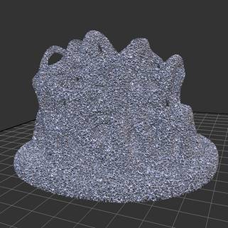
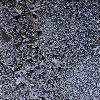
Fig. 1. An implicit foam-like microstructure inspired by [13] filling a complex geometry (model Alien brain by SteedMaker https://www.thingiverse.com/thing:38290)
However, recent researches have shown interesting benefits regarding stochastic microstructures akin to foams [17, ?, 10, 11]. In particular, as they do not follow a global arrangement – there is not underlying regular grid – their properties can be graded and oriented more easily within parts.
While such microstructures can be optimized in large scale problems [22], most of the aforementioned methods rely on functional representations, also known as hypertextures [1]. In this work we will use the generic term implicit solids as we are considering indicator functions that return 0 (empty) or 1 (solid) at every point in space: F : ℝ3 →{0,1}. The function is expected to enforce a number of properties, such as being evaluated in constant time and memory regardless of the point of evaluation [6]. A large variety of 3D structures and effects can be defined in this manner [1]. Usually the function defines an infinite solid covering ℝ3. Thus, a major advantage of functional representations is that they afford for an arbitrary quantity of geometric detail to be defined from a compact, generative algorithm. The parameters of the functions may be varied in space to gradually change the microstructure geometry, and hence control the resulting mechanical properties [10]. Note that this approach extends trivially to multiple materials, by using indicator functions that return 0 for empty, and a material identifier otherwise.
While constant with respect to spatial coordinates, the evaluation cost may still be significant. Thus, it is challenging to interactively visualize the structures during the design process, especially when they are part of a larger, complex design. Similarly, preparing the model for fabrication requires slicing its geometry: decomposing the 3D shape into a set of planar layers that will be fabricated. A typical approach is to first extract a triangular mesh of the geometry, and then feed it to the fabrication software. However, triangle meshes are not well suited when dealing with complex, foam-like structures: Their size quickly grows beyond reasonable even at low tessellation factors. Thus, when dealing with this type of geometries, it is best to consider both interactive visualization and fabrication together.
In this paper, we first describe an approach to visualize foam like microstructures defined as implicit solids and embedded into meshes (Section 3). We then describe an efficient slicing technique for such complex geometries (Section 4).
2. Previous work
A number of prior works have considered the challenges of visualizing and fabricating complex microstructures. Please note that we focus here only on the works most closely related to ours, we invite the reader to refer to recent surveys for a complete overview [3, 12, 9].
Park et al. [16] proposed the use of volumetric, procedural textures for multi-material fabrication, defining both gradients and structures within the parts. Pasko and colleagues [17, 2] explored the use of functional representations to define both periodic and aperiodic structures with graded properties. Slices are generated as images, directly sampling the implicit solid at the coordinates corresponding to the pixel positions in space. Symvol by Uformia also allows to model internal structures with functional representations. It provides interactive feedback through multi-resolution rendering: a blurred view is first produced and progressively refined to reveal the structures. Huang et al. [5] also considered fabrication of implicitly defined solids using images, in particular focusing on preserving the topology of the shapes. Vidimče et al. [21] define a voxel based modeler for 3D printing. Procedural textures can be defined and combined within the object volume. The implicit solids are sampled to produce the slice images streamed to the printer. A hierarchical approach, where voxel size is refined progressively, is used to provide interactive feedback [20]. Lefebvre et al. [7] proposed the concept of slice shaders: they build upon graphics hardware capabilities to apply a pixel shader changing the choice of material within the image of a slice, prior to contour extraction. This allows on-the-fly synthesis of microstructure geometries during slicing; however, the microstructures cannot be visualized beforehand.
3. Modeling and visualization
In this work we model shapes as triangle meshes embedding
implicit solids defined by indicator functions, written as GLSL shader code. We
assume input meshes to be non-self-intersecting, two manifolds: they properly
define the boundary of a finite volume. We also assume that the implicit solid
is r–regular with a known value of r: this implies that sampling the implicit
on a grid of cell size less than ![]() faithfully captures the topology of the
structure [14, 5]. The bound allows to compute a step size to perform
ray-marching in the volume, as described Section 3.1. We focus on implicit
solids defining stochastic, homogeneous volume structures akin to foams. Our
approach extends to other types of structures, but is especially well suited
for this particular case.
faithfully captures the topology of the
structure [14, 5]. The bound allows to compute a step size to perform
ray-marching in the volume, as described Section 3.1. We focus on implicit
solids defining stochastic, homogeneous volume structures akin to foams. Our
approach extends to other types of structures, but is especially well suited
for this particular case.
We discuss in Section 3.2 a first approach for visualization and analyze its drawbacks. We detail in Section 3.3 our approach for gradual rendering of microstructures.
3.1. Ray-marching a r-regular implicit solid
In its simplest form, ray-marching consists in tracing a ray through every pixel, from the near view plane towards the far view plane. The algorithm then marches along the ray, advancing by regularly spaced steps. At each step it queries the value of the implicit solid until a first intersection is found (the indicator function returns 1).
To achieve visually good results, the step size has to be much smaller than the r value of the implicit solid, incurring a large computational overhead. In addition, if the step size is not small enough, swimming artifacts can occur: the surface seems to slightly oscillate as the viewpoint moves. This is due to the change of the precise location of the query points between successive frames.
Our algorithm avoids these issues by building upon the
r-regular property. Instead of simple ray-marching, we perform a DDA algorithm
in a virtual grid having cell size ![]() . Whenever a solid cell is encountered, we
perform a binary search to detect the precise intersection position. This has
the advantage of always sampling the same locations – no swimming occurs –
while using the largest possible step size.
. Whenever a solid cell is encountered, we
perform a binary search to detect the precise intersection position. This has
the advantage of always sampling the same locations – no swimming occurs –
while using the largest possible step size.
The ray-marching algorithm is triggered by rendering a proxy shape – typically a box enclosing the domain where the micro-structure is defined. This invokes a fragment shader in each covered pixel, which then performs ray-marching.
3.2. A first approach
A first approach is to directly perform ray-tracing through both the mesh and the implicit solid. As the implicit is restricted to appear only within the input mesh, the algorithm would locate the two first intersections with the mesh – defining an interior interval of the model – and then perform ray-marching within the implicit along this interval. If no intersection is found, the process resumes with the next solid interval of the mesh.
This is inefficient for two reasons. First, ray-tracing a mesh remains significantly less efficient than rasterizing it using graphics hardware. Acceleration structures have to be built, which can be done efficiently but complicates the task in the context of interactive modeling, where objects change very often. Second, ray-marching will potentially perform a large number of steps before a first intersection is found. This can incur slow, and uneven per-frame rendering times.
3.3. Our approach
To alleviate the difficulties of the aforementioned approach, ray-tracers typically rely on multi-resolution rendering. During interaction a first image is produced with a lower resolution (and hence less rays). As the viewpoint remains fixed the image is progressively refined. Unfortunately, this approach is not very well suited for rendering micro-structures. The foam like geometry quickly averages out when resolution is decreased, and therefore the steps with less resolution do not provide a meaningful preview.
Instead, we propose to gradually display the structures, from front to back. The approach we propose builds upon two techniques. The first is hardware accelerated construction of dexel buffers. The second is the notion of gradual rendering.
Dexel buffer. In our approach, instead of directly tracing rays to find intersections with the mesh triangles, we rely on the rasterizer. We setup the graphics hardware to rasterize all triangles in the view, and record all the fragments produced in a dexel buffer [4]. This operation is both simple and efficient on modern graphics hardware, through e.g. the use of the OpenGL image_load_store extension [8]. This directly retrieves all the solid intervals along the rays, for each screen pixel.
Gradual rendering. Once the dexel buffer constructed, we traverse the solid intervals in order in each pixel, and ray-march them to find the first intersection with the implicit solid, if any.
However, ray-marching remains expensive with uneven per-pixel and per-frame performance. Instead, we propose to ray-march for only a fixed number of steps, from front to back. As the view remains fixed, each next frame will explore a next batch of steps. Each pixel, at each frame, performs the same amount of computations resulting in a stable frame rate. Pixels for which an intersection was already found simply do nothing.
This requires tracking the status of ray-marching in every pixel. We record in an auxiliary buffer, for each pixel, the current position of the raymarcher within the implicit virtual grid. At every frame, each pixel starts by reading its initial position in the buffer and resumes from there. It records its last explored position after having marched the fixed number of steps.
It is interesting to consider the space that is explored at every frame: it is a thick z-slab of the mesh, which is continuous across pixels. The micro-structures we consider are similar to foam and thus homogeneous in space. Many intersections are likely to be found within a continuous slab, and these will overall well capture the local foam geometry, giving a precise visual indication to the user during interaction.
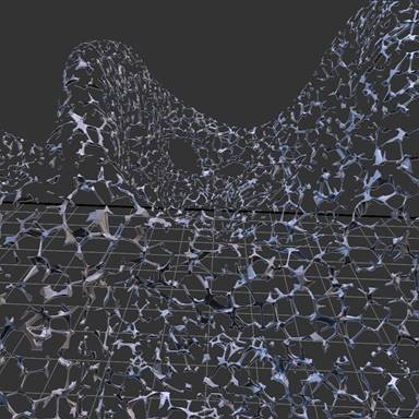
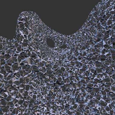
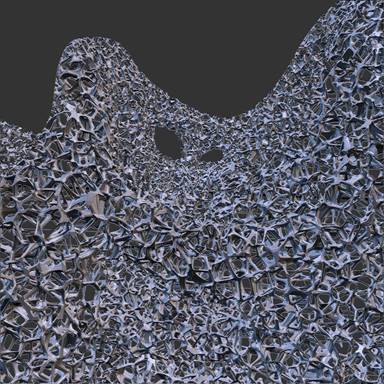
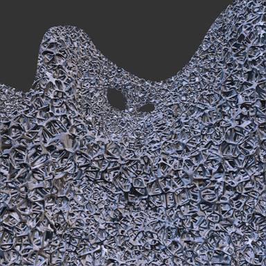
Fig. 2. Gradual ray-marching on the object shown in Figure ??. From left to right: First rendered frame, then frames after respectively 3 sec, 6 sec and 20 sec. Images rendered at 10162 resolution on a GeForce GTX 980. The ray-marching step is 10μm.
Extension to multiple objects. While the principle we described so far works very well for a single mesh and implicit micro-structure, it does not scale directly to a general scenario where multiple shapes filled with microstructures co-exist. In particular, we cannot reasonably use an additional framebuffer to track the ray-marching status of each pixel. To allow for this scenario we introduce dexel tags.
Dexel tags are special records inserted in the dexel buffer. They track meta information regarding, for instance, the ray-marching status of a given implicit primitive. Each dexel entry now tracks both the standard list of fragments, as well as a list of inserted tags.
When the ray-marching shader is invoked in a pixel for a given implicit, it first checks whether a dexel tag is present. If not, this is the first invocation and the shader finds the first solid interval of its proxy shape. If it is present, ray-marching is initialized from the tag, which contains both a pointer towards the last fragment of the current solid interval, and the location from which to resume ray-marching along the ray.
Results. Figure 2 shows the effect of gradual ray-marching across multiple frames. The microstructure is a dense foam filling an object with a moderate geometric complexity (see Figure ?? for a global view). The indicator function is expensive to compute as it involves searching for closest points that are randomly distributed in a virtual grid (see [13] for details). Figure 3 shows another example with a completely different structure, defined by a sine wave perturbed by noise.
Our approach allows for a fast design iteration loop, with immediate feedback and interactive exploration. During a viewpoint change, the rendering shows only a thin slab of the internal structures, but this is sufficient to visualize where the surface is and to grasp a notion of scale. As soon as the view is fixed, the structure is gradually refined. The view is complete after a few seconds (the time depends on the implicit evaluation cost and the marching step).
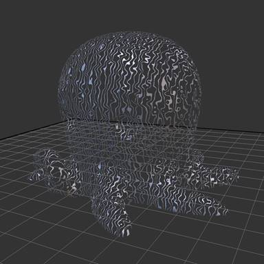
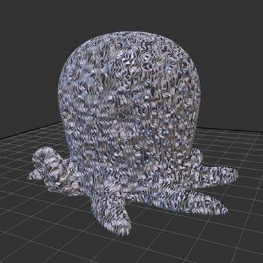
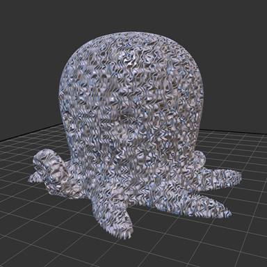
Fig. 3. Gradual ray-marching on the CuteOcto model (thing:27053 by MakerBot). From left to right: First rendered frame, then frames after respectively 1 sec and 4 sec. Images rendered at 10162 resolution on a GeForce GTX 980. The ray-marching step is 10μm, the solid implicit is f(p) = sin(p.x* 6.0+6.0*noise(p*3.0∕4.0)) < 0.75?1 : 0, where noise is a tri-linearly interpolated random scalar field with values in [-1,1].
4. Fabrication
Fabricating foam like structures requires extracting cross-sections of the geometry at every slice. Prior works have proposed to extract images directly from the implicit volume definition [17, 7, 5]. Indeed, each slice can be discretized in a 2D regular grid, which then corresponds to a plane in a virtual voxel grid surrounding the object [21]. By evaluating the implicit solid function at each pixel center, its status (solid/empty) is easily determined. This is illustrated in Figure 4, left.
This may then be directly send to the printer – for instance DLP stereo-lithography machines expect images [17, 21] – or contours can be extracted for further processing [7, 5].
Fully instantiating one image per slice can however be detrimental to performance. Indeed, the images quickly become large: a 100mm3 object using a discretization step of 10μm requires each slice image to be 10000 × 10000 pixels. Directly manipulating these images requires significant memory and bandwidth to track the state of each slice pixel, which slows down processing.
Instead we propose a novel approach to directly extract the cross contours of the solid areas within each slice, in an efficient parallel streaming algorithm. The memory representation is very compact, and its size depends only on the surface area.
4.1. Interval slicing
The core idea of our technique is to efficiently locate the contours of each slice. Instead of working within slices independently, we produce the contours of all the slices simultaneously. Because our output is compact the result usually easily fits in memory. In cases where it does not, our approach can trivially process sub-regions independently, and merge the results.
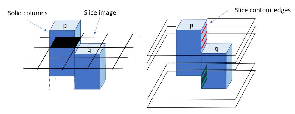
Fig. 4. Left: Each slice can be thought of as an image with pixels either solid or empty. The figure reveals the solid columns produced by the slices for neighboring pixels p and q. One slice image is overlaid, with pixel p in the ’solid’ state. Right: We now consider the contours of the solid areas within the slices, and in this case the edge between p and q. As can be seen, the edge belongs to a contour when the slice is within an interval where either p or q are solid, but not both. In this case there are two intervals, producing the red and green edges in the slice contours.
To understand our approach let us consider an example, shown in Figure 4, right. We consider the contours in the binary images of successive slices. The highlighted edges reveal an interesting property: They are all located on intervals along the two neighboring pixel columns. Our algorithm builds upon this and efficiently computes the intervals of slices supporting edges between pixel columns.
Whenever needed, the edges of a given slice can be retrieved by gathering the intervals including the slice. Each interval corresponds to exactly one (oriented) edge. The edges are then linked back together to form closed contours. This process can be made even more efficient by sweeping through the intervals and producing the edges of all the slices simultaneously.
We describe these ideas in more details below.
Slice intervals. We consider the general case of adaptive
slicing, where slice thicknesses may vary within a same object. The input to
our slicing process is a slicing plan. It is an ordered sequence of slice
thicknesses ![]() =
(t0,...,ti,...,tn). Each slice is identified
by its integer id i. The thicknesses are enough to determine the full sequence
of slicing plane heights: starting from the object bottom, each slicing plane j
is located at height hj =
=
(t0,...,ti,...,tn). Each slice is identified
by its integer id i. The thicknesses are enough to determine the full sequence
of slicing plane heights: starting from the object bottom, each slicing plane j
is located at height hj = ![]() + ∑ i=0j-1ti
(assuming the usual half-slice slicing plane location, without loss of
generality).
+ ∑ i=0j-1ti
(assuming the usual half-slice slicing plane location, without loss of
generality).
A slice interval is simply an integer range of slice ids
[i,j] with j ≥ i. We store slice intervals along each edge of a 2D pixel
grid aligned with the XY axis (with Z the build direction), as illustrated in
Figure 4,
left. We denote by ![]() p,q and
p,q and ![]() q,p the set of intervals on
each side of the face between two neighboring pixels p,q. For clarity, let us
assume now that intervals in a set
q,p the set of intervals on
each side of the face between two neighboring pixels p,q. For clarity, let us
assume now that intervals in a set ![]() p,q do not overlap.
p,q do not overlap.
A slice i belongs to the set if it belongs to one of its intervals:
i ∈![]() p,q ⇔ there exists [s,t] ∈
p,q ⇔ there exists [s,t] ∈![]() p,q such that s ≤ i
≤ t
p,q such that s ≤ i
≤ t
From intervals to edges. Given the intervals we can easily
determine whether there is an (oriented) edge between neighboring pixels p,q at
slice i. Indeed, an edge with positive orientation exists if and only if the
slice belongs to an interval on p’s side and not on q’s side: i ∈![]() p,q and i
p,q and i![]()
![]() q,p. Conversely, there is a
negative orientation edge if and only if the slice belongs to an interval on
q’s side and not on p’s side: i ∈
q,p. Conversely, there is a
negative orientation edge if and only if the slice belongs to an interval on
q’s side and not on p’s side: i ∈![]() q,p and i
q,p and i![]()
![]() p,q.
p,q.
In other words, a positive edge exists if i belongs to
interval in the set difference ![]() p,q \
p,q \![]() q,p, and a negative edge
exists if i belongs to an interval in the set difference
q,p, and a negative edge
exists if i belongs to an interval in the set difference ![]() q,p \
q,p \![]() p,q.
p,q.
This principle can be extended to meshes with self-intersections.
A slice may then belong to multiple overlapping intervals in the sets ![]() p,q and
p,q and ![]() q,p, and
comparing the number of enclosing intervals is sufficient to properly define
edges. The same generalization can be performed on CSG between volumes,
postponing the CSG operations on the slice intervals of the objects.
q,p, and
comparing the number of enclosing intervals is sufficient to properly define
edges. The same generalization can be performed on CSG between volumes,
postponing the CSG operations on the slice intervals of the objects.
Interval construction. Construction is performed with either ray-marching (microstructure) or rasterization (meshes). It is based on the following observation: The z position of an intersection (respectively entry/exit) with the solid is enough to determine one bound (respectively lower/upper) of a slice interval. Therefore, we can traverse the intersections in any order, and record the interval bounds as they are discovered. These are sorted – after traversal or during insertion – to obtain the final intervals.
Let us consider an entry intersection along the ray through
pixel p, at height ze. The id i of the slice enclosing e can be
efficiently retrieved by a binary search in ![]() . Two cases occur. If ze ≤ hi
then the entry occurs below the slicing plane of i and pixel p of slice i is
the first in a solid column. We add a lower slice interval bound [i in
. Two cases occur. If ze ≤ hi
then the entry occurs below the slicing plane of i and pixel p of slice i is
the first in a solid column. We add a lower slice interval bound [i in ![]() p,q for
all four neighbors q. If ze > hi then the entry occurs
above the slicing plane of i and pixel p of slice i + 1 is the first in a solid
column. We add a lower slice interval bound [i + 1 in
p,q for
all four neighbors q. If ze > hi then the entry occurs
above the slicing plane of i and pixel p of slice i + 1 is the first in a solid
column. We add a lower slice interval bound [i + 1 in ![]() p,q for all four neighbors
q. We proceed similarly for exit events, adding upper bounds i - 1] and i]
depending on whether the position zs of the exiting intersection is
below/above the slicing plane height hi. After all intersections are
found, we sort the lower/upper bounds. Note that sorting is not necessary if
intersections are traversed in order, e.g. with ray-marching.
p,q for all four neighbors
q. We proceed similarly for exit events, adding upper bounds i - 1] and i]
depending on whether the position zs of the exiting intersection is
below/above the slicing plane height hi. After all intersections are
found, we sort the lower/upper bounds. Note that sorting is not necessary if
intersections are traversed in order, e.g. with ray-marching.
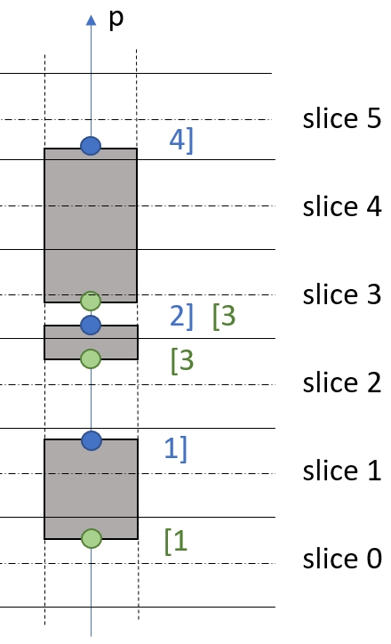
To obtain the final intervals, an additional step is required. Indeed, more than one intersection may occur within a slice thickness. After sorting we cancel pairs of the form i- 1],[i. The remaining bounds form the correct slice intervals. We illustrate an example in the Figure inset. In this case, the slice intervals for pixel p and its neighbors will be {[1,1],[3,4]}.
It is worth noting that the slice intervals do not fully record the geometry: a very complex model will have many more intersections and solid intervals than there are slice intervals. Similarly, as the intervals only require to record slice ids – and not depth – they can be encoded using less precision. For instance, encoding a slice id on 16 bits already allows objects up to 655 cm in height using 10 μm slices.
5. Conclusion
We have introduced two algorithms for visualization and fabrication of foam like structures. These structures are characterized by a very complex yet homogeneous structures at fine scale. Multi-resolution approaches for visualization are not best suited as the lack of resolution quickly hides the local structures. Instead, we proposed a gradual rendering, from front to back. Both our technique and multi-resolution can be employed simultaneously.
We then introduced interval slicing which quickly extracts slice contours by recording slice intervals along the faces of pixel columns aligned with the build direction. This shares the same advantages as image/voxel based approaches in terms of simplicity and parallelism, but provides a much more compact and efficient output, strongly reducing bandwidth requirements.
References
[1] David Ebert, Kent Musgrave, Darwyn Peachey, Ken Perlin, and Worley. Texturing and Modeling: A Procedural Approach. Academic Press, October 1994. ISBN 0-12-228760-6.
[2] Oleg Fryazinov, Turlif Vilbrandt, and Alexander A. Pasko. Multi-scale space-variant FRep cellular structures. Comput. Aided Des., 45(1):26–34, 2013.
[3] Wei Gao, Yunbo Zhang, Devarajan Ramanujan, Karthik Ramani, Yong Chen, Christopher B Williams, Charlie CL Wang, Yung C Shin, Song Zhang, and Pablo D Zavattieri. The status, challenges, and future of additive manufacturing in engineering. Computer-Aided Design, 69:65–89, 2015.
[4] Tim Van Hook. Real-time shaded nc milling display. In Proceedings of the 13th annual conference on Computer graphics and interactive techniques - SIGGRAPH 86. Association for Computing Machinery (ACM), 1986.
[5] Pu Huang, Charlie CL Wang, and Yong Chen. Intersection-free and topologically faithful slicing of implicit solid. Journal of Computing and Information Science in Engineering, 13(2):021009, 2013.
[6] Ares Lagae, Sylvain Lefebvre, Rob Cook, Tony DeRose, George Drettakis, D.S. Ebert, J.P. Lewis, Ken Perlin, and Matthias Zwicker. A survey of procedural noise functions. Computer Graphics Forum, 29(8), 2010.
[7] Sylvain Lefebvre. Icesl: A gpu accelerated csg modeler and slicer. In AEFA’13, 18th European Forum on Additive Manufacturing, 2013.
[8] Sylvain Lefebvre, Samuel Hornus, and Anass Lasram. Per-pixel lists for single pass a-buffer. In GPU Pro 5, pages 3–23. Informa UK Limited, apr 2014.
[9] Marco Livesu, Stefano Ellero, Jonàs Martínez, Lefebvre Sylvain, and Marco Attene. From 3d models to 3d prints: an overview of the processing pipeline. Computer Graphics Forum, 36(2):537–564, 2017.
[10] Jonàs Martínez, Jérémie Dumas, and Sylvain Lefebvre. Procedural Voronoi foams for additive manufacturing. ACM Trans. Graph., 35(4):44:1–44:12, 2016.
[11] Jonàs Martínez, Haichuan Song, Jérémie Dumas, and Sylvain Lefebvre. Orthotropic k-nearest foams for additive manufacturing. ACM Trans. Graph., 36(4):121:1–121:12, July 2017.
[12] Asla Medeiros e Sá, Karina Rodriguez Echavarria, Nico Pietroni, and Paolo Cignoni. State of the art on functional fabrication. In Eurographics Workshop on Graphics for Digital Fabrication, 2016.
[13] Fabrice Neyret. hypertexture - trabeculum. shadertoy.com/view/ltj3Dc, 2015.
[14] Stelldinger P., Latecki L. J., and Siqueira M. Topological equivalence between a 3d object and the reconstruction of its digital image. 29:126–140, 2007.
[15] Julian Panetta, Qingnan Zhou, Luigi Malomo, Nico Pietroni, Paolo Cignoni, and Denis Zorin. Elastic textures for additive fabrication. ACM Trans. Graph., 34(4):135:1–135:12, 2015.
[16] Seok-Min Park, Richard H. Crawford, and Joseph J. Beaman. Volumetric multi-texturing for functionally gradient material representation. In ACM symposium on Solid modeling and applications, 2001.
[17] Alexander Pasko, Oleg Fryazinov, Turlif Vilbrandt, Pierre-Alain Fayolle, and Valery Adzhiev. Procedural function-based modelling of volumetric microstructures. Graphical Models, 73(5):165–181, 2011.
[18] Christian Schumacher, Bernd Bickel, Jan Rys, Steve Marschner, Chiara Daraio, and Markus Gross. Microstructures to control elasticity in 3D printing. ACM Trans. Graph., 34(4):136:1–136:13, 2015.
[19] Ole Sigmund. Tailoring materials with prescribed elastic properties. Mechanics of Materials, 20(4):351–368, 1995.
[20] Kiril Vidimce, Alexandre Kaspar, Ye Wang, and Wojciech Matusik. Foundry: Hierarchical material design for multi-material fabrication. In ACM User Interface Software and Technology Symposium, 2016.
[21] Kiril Vidimče, Szu-Po Wang, Jonathan Ragan-Kelley, and Wojciech Matusik. Openfab: A programmable pipeline for multi-material fabrication. ACM Transactions on Graphics, 32, July 2013.
[22] Jun Wu, Niels Aage, Rüdiger Westermann, and Ole Sigmund. Infill optimization for additive manufacturing–approaching bone-like porous structures. arXiv, 2016.