CRYPTOGRAPHIC METHOD OF THE PICTURES DOCUMENTING
D.A. Melnikov, A.A. Abramov, V.S. Gorbatov, A.P. Durakovskiy, R.D. Makhmutov
National Research Nuclear University "MEPhI" (Moscow Engineering Physics Institute), Moscow, Russian Federation
DAMelnikov@mephi.ru, mvpcvp@gmail.com, VSGorbatov@mephi.ru, APDurakovskiy@mephi.ru, infmaxx@gmail.com
Contents
2. The method of a reusable geometrical rearrangement
3. Methods of geometric alternation of SPIM
4. The complication of permutation: multidirectional contour rotation
5. Some aspects of practical implementation
Abstract
Today one of the directions of data technology development is a visualization, i.e., a representation of something - a physical process, a phenomenon, etc. in a form convenient for viewing [1]. Visualization became widespread in many practical areas, one of which is the digital forensics. In the latter one began to use the visual evidences very actively. In case of any crime the visual evidence plays a vital role for a realization of the punishment inevitability principle. However, the visual evidences have a digital nature and therefore require specific protection measures to be applied to stand any kinds of its modifications. In some cases, one might need to protect privacy of the visual evidence, particularly, if it contains information constituting a state or commercial secret or personal data.
On the other hand, the visual evidence has to confirm the fact of violation while not allowing an offender to desist from any action or inactivity confirming this fact. In this case, the judge may ask for visual evidence to make her/his mind about the fact of violation of the law.
The paper discusses the major ideas and approaches to practical implementation of the cryptographic method to ensure the integrity and confidentiality of images (visual evidence) - so called the method of Melnikov-Jones [2]. In addition, this method can be used for formation and protection of visual evidence in the resolution of legal disputes (to assure non-repudiation). This method is based on the preparatory scrambling and several subsequent geometric permutations of pixels of the image via its decomposition using a triangular lattice, that virtually eliminates any possibility of malicious distortion. In other words, any attempted modification of the visual document will be detected.
Keywords: visual evidence, data forensics, triangular lattice, geometric permutation, hexagon, rotation angle, permutation, scrambling, cryptography, encryption, integrity, modification.
1. Introduction
Currently, there is increasing use of multimedia tools to collect documentary evidences for jural conflict resolution. One of the main requirements is the existence of certain assurances for integrity of the evidence presented, which is achieved by one or another means of protection against forgery.
One of the visual evidence protection technique developing directions is the use of so called the digital watermarks (DWM). DWM is a steganography’s mechanism of data protection [3,4]. The main disadvantages of such DWM systems are as follows: first, a DWM impacts directly on the protected visual evidence, i.e., destroys evidence, but it is not acceptable from the point of view of the receiving and storage of physical evidences. And, second, cryptographic resistance of the DWMs is very weak, i.e., they are easily detected (e.g., by inserting a monochrome image) and can be modified.
Another technique to protect the visual evidence is the use of digital signatures (DS). A DS protects the evidence from modification and identifies the author of the DS itself [5]. However, DS does not protect the confidentiality of the evidence if it includes information containing official or commercial secrets.
In this article, we consider one of the cryptographic methods to protect the integrity (of the document) of a static image based on the procedure of scrambling the initial sequence of dots (pixels) in the image (PIM) and its geometrical rearrangements.
Any static image is a sequence of pixel, each having its own color. The range of colors can be different and depends on the particular type of color encoding. Since any image has a large information redundancy, as a rule, it is subjected to the compression procedure (in accordance with the selected compression algorithm) and in this form, either stored in a memory of one or another device on the electronic media, or transmitted via communication channels.
One of the most reliable mechanisms to protect single-shot images is the usage of the encoding procedure implemented as follows. The sequence of the PIM (SPIM) represented in binary code is summed by mod 2 with the output sequence of the generator cipher. It should be noted an important feature of the resulting SPIM: it keeps the initial order of movement of the PIM. In [2,6] it is shown that for reliable protection algorithm single-shot images is necessary to solve two problems:
1) to exclude any correlations (statistical) between adjacent and nearby pixels in the image [7];
2) to exclude any recursive properties of the stream (block) cipher [5].
To resolve the first problem, one can use linear or nonlinear scrambler based on a finite state automation (cipher), which has good statistical properties [5].
The scrambling procedure removes the correlations between the PIM. However, due to the fact that the scrambler represents a finite state automation, the scrambled initial SPIM (ISPIM) will have recurrent properties that are determined by the generator polynomial automation. In addition, the modified during the process of scrambling ISPIM will keep the natural order of PIM that also reduces the stability of the proposed single-shot image protection method. Therefore, the second step is to eliminate these recurrent properties of the scrambled ISPIM along with the natural order of PIM in it. These conditions can be fulfilled by the geometric multiple permutations of the scrambled ISPIM.
2. The method of a reusable geometrical rearrangement
To solve the second problem, we proposed to exclude the application of any algebraic structures, and to use only geometric techniques to interleave PIM. To do this, at the beginning, put a triangular lattice on a square image pixel image (Fig.1).
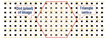
Fig. 1. The image (pixels) with the applied triangular lattice (pixels in the form of a square lattice)
Fig. 2 shows the different partitions of PIM located at the nodes of a triangular lattice [8]. In the given case, the splitting and/or grouping of the PIM is based on the choice of the hexagon Hn with side equaled to n PIM, i.e. with the chosen side length of the hexagon measured in PIM. Fig. 2 shows four such hexagons H2, H3, H4 and H5. Each of these hexagons includes 7, 19, 37 and 61 PIM. Let's consider the value of Sn, defined as the number of PIM included in Hn, which is determined by the following formula:
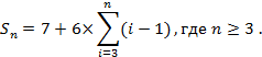
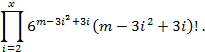
For example, for a hexagon with a side of 7 PIM the total number of PIM covered by this hexagon are equal to:
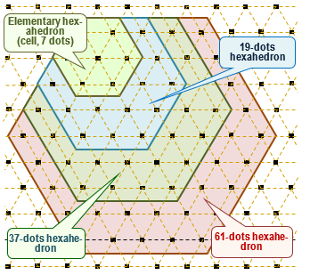
Fig. 2. Elementary (7-dots), 19-, 37 - and 61-dots hexahedrons (the pixels are structured in the form of a triangular lattice)
![]()
For determining the number of PIM included in a hexagon with side equal to n PIM you can use another formula as well. For example, for a hexagon with a side of 7 PIM one could write a sequence of numbers: 7 8 9 10 11 12 13 12 11 10 9 8 7. Each of the numbers indicates the number of PIM in each row (number of rows is 2n – 1) of the hexagon. Then the formula to determine the number of PIM in the hexagon would be:
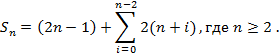
However, there is a more general formula to determine the number of PIM inscribed in a hexagon with side of n PIM:
![]() .
.
With the help of such hexagons, you can build quite a large number of various mosaic shapes or “matrices” with different patterns (Fig. 3, a). It should be noted that the matrix can be based on hexagons of different sizes and possess asymmetric patterns (Fig. 3, b).
In the simplest case, to interleave the ISPIM let’s inscribe it, for example, in H4 (S4 = 37 PIM, Fig. 4) and then rotate it on various permissible angles (60°, 120°, 180°, 240°, 300°). After the rotation let’s read the resulting SPIM again. The resulting sequences for different rotation options are presented in Fig. 4. It should be noted that the rotations on 60° and 240°, and 120° and 300° are dual, that is, the newly formed SPIMs for each pair of rotations are of reverse order.
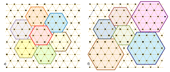
Fig. 3. Examples of two different mosaic shapes (matrices): a) symmetric; b) asymmetric
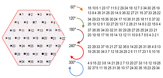
Fig. 4. Example of hexagon H4 and the resultant sequences after rotation of the hexagon
Thus, all of the ISPIM (protected image) can pass through the selected hexagon and repeat this process several times with different hexagons.
It is obvious that the example of the alternation of the ISPIM on the basis of only one hexagon H4 is very simplistic and is intended only to demonstrate the procedure of permutation. In real systems, can be used very diverse mosaic pattern matrix based on different hexagons with respect to their size. In such matrices, of course, the number of covered points will exceed the real number PIM. At the same time the order of inscribing of the ISPIM in a matrix, the reading order of the points from the matrix after performing its rotation (rotation of the hexagons), the rotation angles of the hexagons in the matrix, the number of matrices used and their sequence during the permutations of SPIM can be different and depend on the specific implementation of the considered method.
When the procedure of interleaving PIM using all the matrices is completed, the result is a final sequence which can serve as a mapping table (MT) of the ISPIM into a new interlaced sequence.
3. Methods of geometric alternation of SPIM
The options for partition SPIM can be very different, but, nevertheless, all the features are based on the following methods.
1) TI is represented as a rectangular matrix (grid) and hexagons are selected for it and then a permutation of these hexahedrons in the form of rotation takes place (Fig. 1).
2) TI can be represented by triangular matrix (lattice) in which items are selected in the shape of internal hexagon. Then a permutation of these elements represented by a rotation of each internal hexagon (Fig. 2 and Fig. 4)
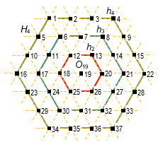
Fig. 5. Examples of contour hexagon h4, h3 and h2
3) PIM is considered as a string, in which is permutation is equivalent to a permutation of rotation of hexagon for consecutive elements.
4) PIM are considered as a ring, in which a permutation is equivalent to permutation of rotation of a hexagon for consecutive elements.
Before to make a comparative analysis of these methods for interleaving, consider the hexagon H4 in Fig. 5. We will call a contour hexagon hn of dimension n such PIM that belong to a face of the hexagon hn consisting of Sn, PIM. That is, the hexagon H4 in Fig. 5 consists of three contour hexahedrons h4, h3 and h2 and the Central element O19. Then the number of PIM in hn is calculated according to the formula 6(n – 1) and, therefore, minimal contour hexagon is h2. Rotation of the hex is only possible at acceptable multiples of 60°, because the faces of the hexahedron are composed of PIM with fixed positions. In other words, rotation by an arbitrary angle is impossible, since the definition of new TI positions, in this case, would be extremely difficult, particularly when using a square grid.
Now let's analyze the rotation contour of the hexagon h3
is 60°, represented in Fig. 6. Writing PIM in a row, we get: 1 2 3 4 5 6 7 8 9
10 11 12, after the rotation we have 11 12 1 2 3 4 5 6 7 8 9 10 (![]() ). The
procedure presented here corresponds to a cyclic shift (n–1) PIM, where
n is the number of PIM in a face hn. Thus, the rotation of
the hexagon Hn is the shift on m–1 PIM of each of n–1
contour hexagons with a dimension m, where
). The
procedure presented here corresponds to a cyclic shift (n–1) PIM, where
n is the number of PIM in a face hn. Thus, the rotation of
the hexagon Hn is the shift on m–1 PIM of each of n–1
contour hexagons with a dimension m, where ![]() , and m
is an integer. That is, the permutation (rotation) of the hexagon Hn
can be decomposed into the composition of permutations (rotation) of the
contour of the hexagons that are part of the hexagon Hn.
, and m
is an integer. That is, the permutation (rotation) of the hexagon Hn
can be decomposed into the composition of permutations (rotation) of the
contour of the hexagons that are part of the hexagon Hn.
The first and second modes of alternation differ in a shape the data are organized: in the first case it is a square matrix, and the second is triangular. The advantage of a form of data organization as a triangular lattice is missing of movable PIM. In the case of square lattice, the four PIM, which are in the corners of the matrix, guaranteed fixed, as there is no hex into which they were included. The rest of these approaches are the same and require the use of only two simple operations to implement the rotation:
· the choice of PIM, which belong to the hexagon Hn by its center point On;
· permutation of selected PIM in accordance with the desired rotation angle of the hexagon.
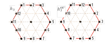
Fig. 6. The rotation contour of the hexagon h3
Consider the third way of alternation of PIM. If we consider the PTI as a string, then the first TI will be fixed and as it is not involved in the permutation, but only defines the beginning of a line (PTI) and it could be dismissed.
Then the number of elements in the hexagon will be: ![]() where
n – is the number of PIM in facets in the hexagon. Let m be the
number of points in the image, x is the maximum integer satisfying the
condition:
where
n – is the number of PIM in facets in the hexagon. Let m be the
number of points in the image, x is the maximum integer satisfying the
condition: ![]() . For
hexagon consisting of
. For
hexagon consisting of ![]() PIM
there exists m – k different positions in SPIM, in each it can be
rotated at 6 different angles (including 0°), i.e. for the first hexagon of
dimension n there are
PIM
there exists m – k different positions in SPIM, in each it can be
rotated at 6 different angles (including 0°), i.e. for the first hexagon of
dimension n there are ![]() conditions, for the second
conditions, for the second ![]() and so on. Thus, the
number of possible States only for the hexahedrons consisting of k PIM:
and so on. Thus, the
number of possible States only for the hexahedrons consisting of k PIM:
![]()
Since k may be different and you can use any combination of unequal hexagons (even having the same center), then a total number of combinations:
Assume there are z zeros in a bit representation of image with y length, then the number of different images that can be obtained from the original image, will not be more than
![]()
Thus, the number of different images that will be the result of a permutation depends on the original image. The maximum of images is when z = y/2. It is obvious that the number of permutations exceeds the number of different images. This problem can be solved by increasing the bit length TI of the permutation, it will reduce the number of permutations and reduce the number of permutations leading to the same result.
Now consider the fourth way interleave of PIM. By
analogy with the previous arguments we obtain that the number of permutations
for hexs the size k of the image of size m will be: ![]() , a
total number of permutations
, a
total number of permutations ![]() ,
which further exceeds the number of available states of the image. This problem
can be solved also by increasing the PIM bit length. However, in case of
implementation of the fourth principle of alternation the identical
permutations, which are associated with the representation of the image in the
form of a ring are inevitable.
,
which further exceeds the number of available states of the image. This problem
can be solved also by increasing the PIM bit length. However, in case of
implementation of the fourth principle of alternation the identical
permutations, which are associated with the representation of the image in the
form of a ring are inevitable.
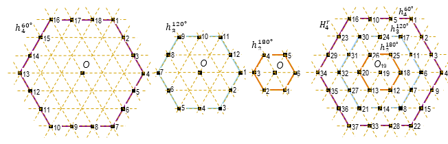
The resulting PTI: 16 10 5 1 23 30 24 17 2 29 31 26 25 11 3 34 32 20 19 18 6 4 35 27 13 12 7 9 36 21 14 8 15 37 33 28 22
Fig. 7. Examples of contour hexagons h4, h3 and h2, which have different rotation angles (60°, 120°, 180°; the original H4 is presented in Fig.5)
A common drawback of the third and fourth ways of interleave of the PIM is that the image is poorly “mixed” vertically and quite good “mixed” horizontally. This is due to the representation of the image as a string, which greatly simplifies the implementation process, however, significantly affects the quality of the result of the alternation procedure. Based on the foregoing, it is recommended to use the second way of permutation of PIM.
4. The complication of permutation: multidirectional contour rotation
Decomposition of any hexagon Hn on a set
of contour hexagons hm (![]() )
allows you to complicate the procedure of rotation of the original hexagon,
that is, the procedure of permutation of the ISPIM. Fig. 7 shows an example of
a contour multi-directional rotation of the hexagon H4. All
contour hexahedrons h4, h3 and h2,
included in the hexagon H4, have different angles of
rotation:
)
allows you to complicate the procedure of rotation of the original hexagon,
that is, the procedure of permutation of the ISPIM. Fig. 7 shows an example of
a contour multi-directional rotation of the hexagon H4. All
contour hexahedrons h4, h3 and h2,
included in the hexagon H4, have different angles of
rotation: ![]() и
и ![]() . In
this example, each of the rotation angle in multiples of 60°, increases
consistently with decreasing side contour of a hexagon.
. In
this example, each of the rotation angle in multiples of 60°, increases
consistently with decreasing side contour of a hexagon.
Obviously, if the hexagon Hn will
have a side n >> 4, and
accordingly, the number of its constituent contour of the hexagons will be n
>> 3, the angles of rotation of
each contour of the hexagon hn can get arbitrarily
decreasing. Fig. 8 shows the hexahedron H8, the seven
contour of the hexagons with the corresponding angles of rotations: ![]()
![]() and
and ![]() , and
ISPIM as well.
, and
ISPIM as well.
Fig. 9 shows examples of permutation pixels of the real image (Fig. 9, a). When interleaving the ISPIM one had used a lot of hexagons:
![]() , where
, where
![]()
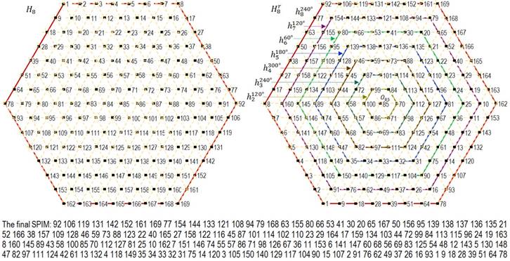
Fig. 8. An example of multidirectional rotation of the hexahedron H8, and the final SPIM
For each case permutations 50 (Fig. 9, b), 100 (Fig. 9, c), 200 (Fig. 9, d), and 300 (Fig. 9, e), hexagons were used. In addition, for all permutation options the angle of rotation, the starting point and the size of the hexagon (from the set H) were selected randomly.
5. Some aspects of practical implementation
Consider another example of implementation of the proposed method of the static image protection (Fig. 10). Fig. 10,a shows a source image that has the following specifics: the whole picture is black and white, except the eyes of the tiger.
|
a) |
b) |
|
c) |
d) |
|
e) |
|

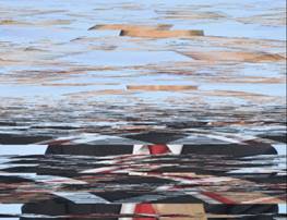
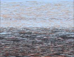
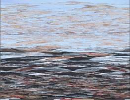
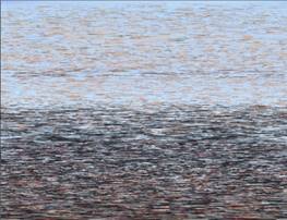
Fig. 9. Examples of alternation SPIM using 50 (b), 100 (c), 200 (d) and 300 (e), hexagons
Fig. 10,b shows the result of additive scrambling of the original SPIM, that is an addition by mod 256 of each pixel octet in the original SPIM with a pseudo-random number (octet). In this example, we used a linear congruential generator:
![]()
with the following coefficients: m = 232, a = 1664525, c = 1013904223. Obviously, you can use any other pseudo random number generator with good statistical properties. It should be noted that in Fig. 10,b the outlines of the original image of the tiger are still visible, namely the contours of the eyes.
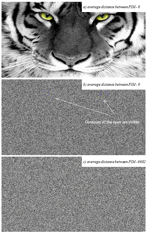
Fig. 10. An example of protection of a static image. Source (a), scrambled (b) and the result (c)
Fig. 10,c shows the final image formed from the resulting SPIM, which was obtained by alternation of scrambled SPIM. It should be noted that as a result of this interleave with the number of iterations amounting to 20, the distance between nearby PIM of the original image has increased to 6682 positions an average.
For permutations scrambled SPIM we have used the following set of hexagons:
![]() , where
, where
![]() ,
,
what is 7351...18961 pixel of the original image.
In the practical implementation of the single-shot documentation method presented here in order to ensure a reliable level of security it is appropriate to comply with the following recommendations:
1. Initial seeding vector (ISV) of the scrambler and the mapping table (MT) pertain to the confidential data, that is to be protected from unauthorized access (UAC).
2. For the MT formation, it is necessary to use several matrices of mosaic (the more the better) with different pictures, different hexagon sizes and different angles of rotation of the latter, as well as the various options of inscribing the SPIM within a matrix and reading PIM from it. All the original data for the formation of MT also possess the property of confidentiality and in fact are the basis of the algorithm for its generation.
3. When designing a hardware-software complex it should be divided into two functional modules:
1) a generation module (GM) of MT and the ISV of the scrambler;
2) an encryption module (EM) for static images using the available MT and ISV.
4. For each EM pair (for two cooperating users) its own unique array of MT and ISV is generated (each MT corresponding ISV) in two copies stored on two electronic storage devices, one for each user.
5. GM should be placed in a special secure room.
These requirements will provide users with a high level of protection of static images, even if another pair of EM has been compromised.
6. Conclusion
Modern advances in the visualization technologies are primarily driven by the growth of their practical importance. In particular, the visualization technologies have found its broad application in digital forensics. The visual evidence plays a vital role for a realization of the punishment inevitability principle.
The article describes a cryptographic protection method that ensures integrity and confidentiality for the visual evidences. This method is based on the preparatory scrambling and several subsequent geometric permutations of pixels of an image by its partitioning using a triangular lattice.
The article also presents a preliminary assessment of the durability of this method, that has demonstrated good results. That is, even if an attacker [9,10] possesses the original frame and its encrypted analogue, then it would be very difficult (from the point of view of computational costs) for him to determine the number and figures of the mosaic matrices used for the message encoding, namely, the algorithm of the TO formation, and, consequently, to distort the source image (visual evidence) for illegal use.
References
1. Ballard D., Brown C. Computer Vision. Prentice Hall, Englewood Cliffs, NJ, 1982.
2. Melnikov D., Jones A. Static Image Data Hiding and Encryption Method. Proceedings of the 3rd European Conference on Information Warfare and Security. Royal Holloway University of London, UK. 28-29 June 2004. p. 279-284.
3. Osborne C., van Schyndel R., Tirkel A. A Digital Watermark. IEEE Intern. Conf. on Image Processing, 1994. P. 86-90.
4. Gribunin V.G., Agranovskij A.V., Balakin A.V. Steganografija, cifrovye vodjanye znaki i steganoanaliz [Steganography, digital watermarking and steganalysis]. Vuzovskaja kniga, 2009. [In Russian]
5. Alferov A.P., Zubov A.Ju., Kuz'min A.S., Cheremushkin A.V. Osnovy kriptografii [Basics of cryptography]. Gelios-ARV, 2002. [In Russian]
6. Mel'nikov D.A. Metod zashhity nepodvizhnyh izobrazhenij [The method of protection of still images]. Informacionnye tehnologii upravlenija v social'no-jekonomicheskih sistemah. 2010. No 4. pp. 130-139. [In Russian]
7. Babash A.V., Shankin G.P. Kriptografija [Cryptography]. SOLON-R, 2002. [In Russian]
8. Conway J.H., Sloane N.J.A. Sphere Packings, Lattices and Groupsju Springer-Verlag, New-York, 1988.
9. Kahn D. The Codebreakers. MacMillan. New-York, 1967.
10. Denning D. Cryptography and Data Security. Addison-Wesley, Reading, MA, 1982.