IMPROVING VISUALIZATION QUALITY OF THE HOMOGENEOUS VISUAL ENVIRONMENT
M. V. Martynyuk, E. S. Kadilenko, S. G. Chanova, K. A. Prokofieva, D. R. Timofeev, D.I. Zhurba, V. S. Naumov *
Nizhny Novgorod State Technical University named after R.E. Alekseyev, N. Novgorod, Russia
*Moscow State University of civil engineering, Moscow, Russia
m_mart@mail.ru, evgeny.kadilenko.mera@gmail.com, sv_chanova@mail.ru, ks.prokofjeva@gmail.com, td.renatovich@mail.ru, arhans2012@gmail.com, naumov48@mail.ru
Content
2. Analysis of the available solutions
3. Detection of low-contrast objects edges on the image
4. Underlining of low-contrast edges
Annotation
We propose an algorithm to search and underline the edges of low-contrast objects in the image. The image is brought to the form that contributes to less fatigue of a viewer during the prolonged observation. A distinctive feature of the algorithm is that the changes made to the frame are minimal, and the results of its application are clearly visible in the low-contrast images and almost invisible in the high-contrast images. By its action the algorithm resembles manual retouching of the photos.
The article illustrates the main stages of the algorithm and gives evaluation of its operation speed. The work contains the results of processing of several graphics files and videos.
The proposed algorithm can be used in the system of technical vision of the vehicle for better visualization of the surrounding area in poor visibility conditions. It can also improve the perception of poorly lit areas of space without the use of additional lighting.
This work was financially supported by the government in the face of the Russian Ministry of Education (the unique identifier of the project: RFMEFI57414X0055).
Keywords: image processing, Canny method, image gradient, "Skeletonization" of binary image, computer vision system.
1. Introduction
Visual perception is a complex psycho-physiological process; one of its stages is the analysis that is detection of objects from the background of perception [1]. Detection of the object is performed partly on the basis of the contrast between the object and the background. Monitoring blurred objects for a long time leads to fatigue of the observer. One of the laws of perception is due to the fact that we are unable to percept and keep in mind unchangeable information. Constant stimulus of moderate intensity ceases to be perceived (for example, clothing, watches), monotonous repetition of the same phrase is used to deny its meaning and the so-called emptiness of consciousness [1].
In this paper, we describe the algorithm converting low-contrast (homogeneous) images to the form that contributes to less fatigue of the observer during long observation. The changes in the original image are minimal (the algorithm seeks to comply with the principle of the Hippocratic "do no harm").
This algorithm in the future can be used for imaging of the cameras with off-road vehicles, designed to operate in Arctic conditions.
2. Analysis of the available solutions
There are many methods of "improving the quality of" difficult-to-image picture, in particular, filtration in order to improve contrast or underscore edges, contrast adjustment, and even manual retouching [2]. Obviously, that manual processing is unacceptable, and any kind of filtering results in distortion of the entire image, including in those areas where it is not needed. This increases the contrast of low-contrast objects and "blurring" of well-defined objects. For example, convolution with the Unsharp Mask (USM) - unsharp masking [2], making the image more "grainy" (see. Figure 1c), making it difficult to percept by the observer.
Among the methods of non-linear image processing we can identify photo-comics transformation [3]. Processed so the image looks more detailed, sharp and contrast (Figure 2). However, emphasis of all objects equally can disorient the viewer.
|
a) |
|
|
b) |
|
|
c) |
|

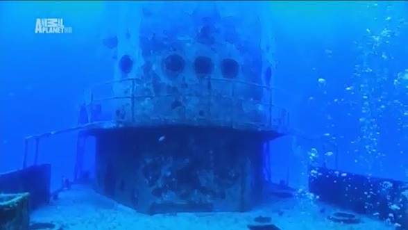
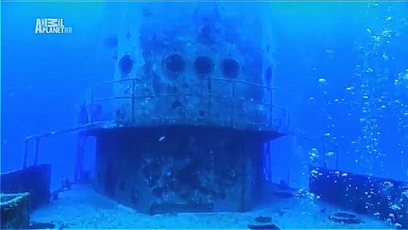
Fig. 1. Examples of the image enhancement application methods [4]: a – the original image; b – application of the method described in this paper; c – application of Unsharp Mask
a) |
|
|
b) |
|
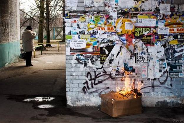
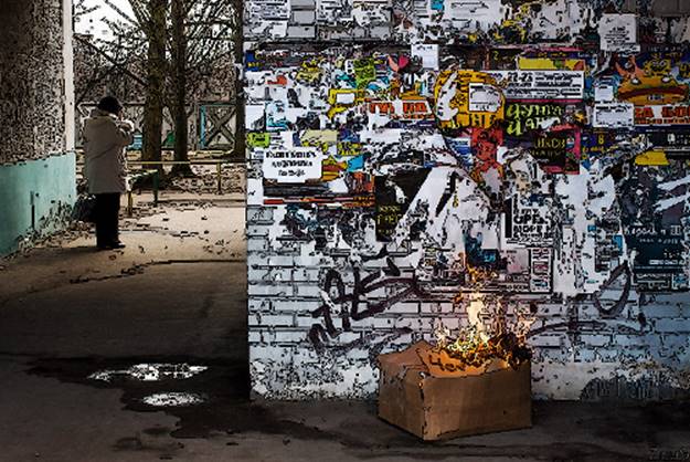
Fig. 2. Illustration of the photo-comics transformation [5]: a – the original image; b – transformed image
The basic idea of the proposed method is to find the image of low-contrast objects and underscore their edges. Objects which are quite different from the surrounding background by their color or light conditions (i.e., "clearly distinguishable") are not emphasized further. In order not to "overload" the image of a large number of items, the objects that almost blend into the background also remain unchanged.
3. Detection of low-contrast objects edges on the image
The degree of contrast / distinguishability is determined on the basis of the image gradient. This algorithm is performed in several steps.
Step 1: Calculation of the image gradient.
Standard color red-blue-green coordinate system, which stores and processes images is not uniform chromatic. This means that the same changes of color coordinates may correspond to different changes of color sensations. Therefore, to compute the gradient, the original image is converted into the CIE Lab color coordinate system. It is uniformed in perception, that is, so that the same changes in each of the coordinates lead to noticeable changes in the same color, so the distance between colors is calculated by the formula
![]()
where![]() – is the
difference of the corresponding color component.
– is the
difference of the corresponding color component.
Each color component is smoothed by a Gaussian filter with standard deviation (σ) - proportional to the angular size (in pixels) of the minimum object of interest of the observer. The larger σ is the longer the filtering and the smaller items will be on the smoothed image. The purpose of smoothing is the weakening of the high-frequency component, which will be increased by further differentiation, as well as elimination of small and insignificant details. This is particularly important if the picture is on the water surface covered with small waves.
Further, for each color component (for example, L (i, j)) differentiation between the lines and columns is performed. Strictly speaking, we calculate approximation of the derivative of color components in lines and columns, as a result of the convolution with mask linear filters [6]:
![]() and
and ![]() .
.
The results of the differentiation of each color component of the original image (see. Figure 3) are used to calculate the modulus of the image gradient (see. Figure 4):
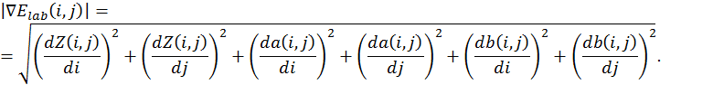
Step 2. Selection of low-contrast edges
To highlight the edges in the original image (see. Figure 3) the Canny method is used, which is considered one of the best edge detectors [7]. Using this method all the essential edges on the original image are indentified (see. Figure 5). The set of points (pixels) belonging to obtain edges are denoted as C.
Further, among the edges found by the Canny edge detector, edges of the blurred objects are detected.
As mentioned above, high-contrast edges (edges of
well-defined objects) and the edges of small objects or the objects merged with
the background (which can be attributed to noise) are not distinguished.
Low-contrast objects requiring additional underscores, we consider the edges
for which ![]() ranges
ranges ![]() . For
. For ![]() and
and ![]() the
following values were selected experimentally:
the
following values were selected experimentally:
![]() = 8%
from maximum value
= 8%
from maximum value ![]() on
the whole image;
on
the whole image;
![]() = 20%
from maximum value
= 20%
from maximum value ![]() on
the whole image.
on
the whole image.
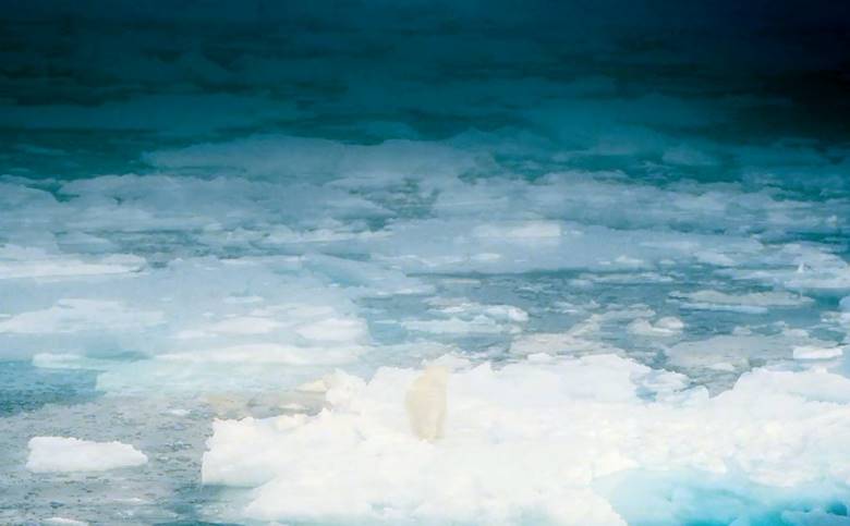
Fig. 3. The original image [8]
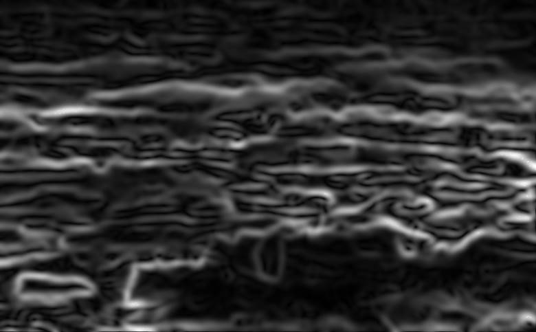
Fig. 4.
Uniform chromatic gradient ![]() of
the image from Fig. 3
of
the image from Fig. 3
From the set of C points (Figure 5), the
points are excluded for which the gradient values are outside the range ![]() (Figure
6). The decimated set of C points contains a lot of
"extra" edges and requires additional decimation (see. Figure 5).
(Figure
6). The decimated set of C points contains a lot of
"extra" edges and requires additional decimation (see. Figure 5).
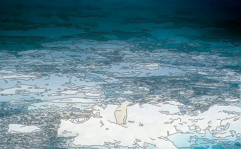
Fig. 5. The result of work of the Canny edge detector
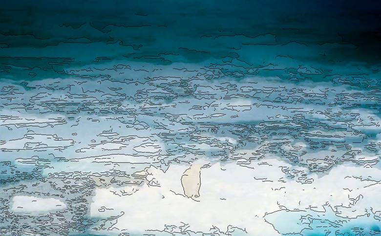
Fig. 6. Canny edges for which the
gradient module ![]() is
within the range
is
within the range ![]()
It turned out that it is difficult to distinguish between
low-contrast edges from the area of high-contrast edge with a small value of the
gradient. If you compare the edges with ridges on the "gradient map"
(Figure 4), this problem can be formulated as the problem of distinguishing
between "low mountain ridge", the height of which is in the range
from "the foot of a high mountain ridge" (the top of which is higher
than ![]() , but
the slope certainly has a plot with height in the range of
, but
the slope certainly has a plot with height in the range of ![]() (Figure
7 and 8). The problem was solved by the method of "scel"
("skeletonization"). This method removes the pixels on the edge of
connected regions, but it does not allow the area to
"disintegrate".Of the modulus of the gradient
(Figure
7 and 8). The problem was solved by the method of "scel"
("skeletonization"). This method removes the pixels on the edge of
connected regions, but it does not allow the area to
"disintegrate".Of the modulus of the gradient ![]() binary
images B1 and B2 are being formed based on logical conditions:
binary
images B1 and B2 are being formed based on logical conditions:
(see. Figure 7) and
№2: ![]()
(see. Figures 8).
To binary images B1 and B2 the method of
skeletonization is applied (Figure 9 and 10). The skeletonized image B1
corresponds to the "ridges" of low-contrast and high-contrast edges.
The skeletonized image B2 corresponds to the "ridges" of low-contrast
and "slopes" high-contrast edges. Intersection of skeletal images B1
and B2 (see. Figure 11) corresponds to the "range" of weak edges, the
gradient of which lies strictly in the range ![]() (Figure
12).
(Figure
12).
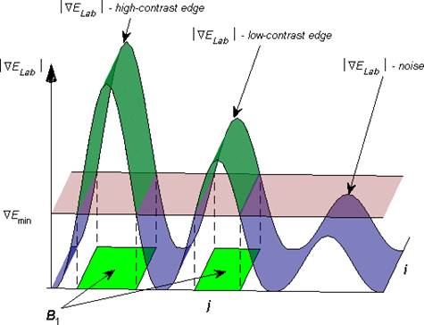
Fig. 7. Illustration to the forming of the binary image B1
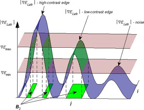
Fig. 8. Illustration to the forming of the binary image B2
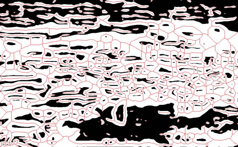
Fig. 9. A binary image B1 (b / w) and the result of skeletonization (red)
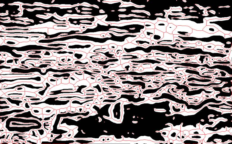
Fig. 10. A binary image B2 (b / w) and the result of skeletonization (red)
The final result, then low contrast edges (see. Figure 8), are obtained as the intersection of weak borders (Figure 12) and decimated set of C points (Figure 6).
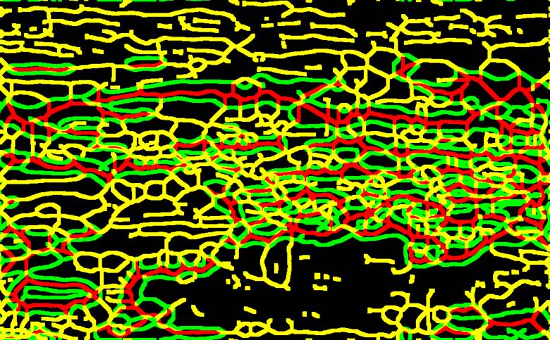
Fig. 11. Skeletonized binary image B1 (red), B2 (green) and their intersection (yellow)
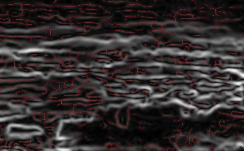
Fig. 12. Weak edges (red) on the background of the image gradient
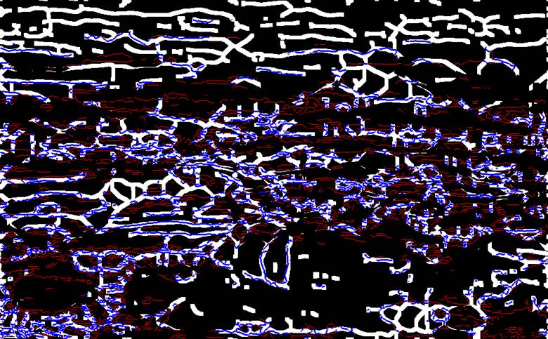
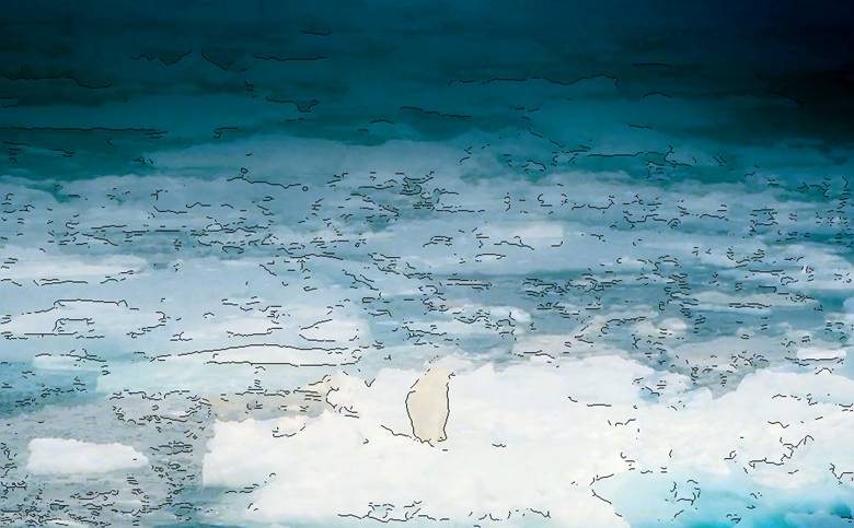
Fig. 14. Low-contrast edges (black color) on the background of the original image
4. Underlining of low-contrast edges
After obtaining the set of points belonging to the low-contrast edges they must be displayed in such a way that they do not interfere with the perception of the rest of the image. We tried several approaches. The best result (including in terms of preserving the perceptual quality of the images with high contrast) was obtained with decreasing of the intensity by 7.7% (of each color component) of the dark pixel and increasing by 3.5% of the intensity of the brightest pixel in a single area of each of the points from the set of C points. (I.e. the points belonging to the low-contrast edges). The area of the unit is the region of nine pixels forming a square with center at the given point.
Some examples of implementation of this technique for the low-contrast image (Figure 15¸17, 21, 22), image of medium contrast (Figure 18) and high-contrast images are given (Figure 19).
|
a)
|
b)
|

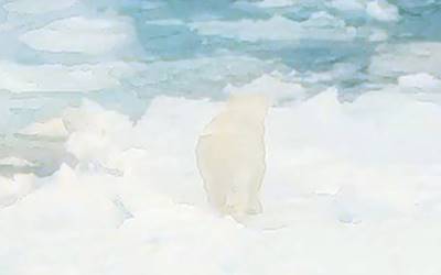
Fig. 15. An example of the method to the part of low-contrast image: a – the original image, b – application of the method described in this paper
|
a)
|
b)
|
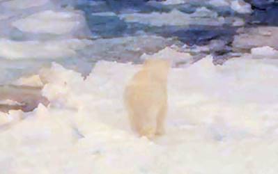

Fig. 15. An example of the method to the part of low-contrast image after color correction: a – the original image, b – application of the method described in this paper
a) |
|
|
b) |
|

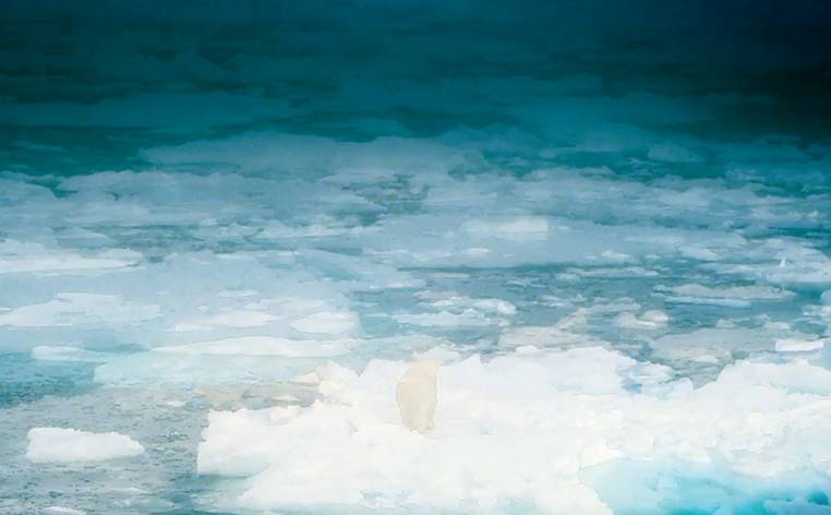
Fig. 17. An example of the method to the low-contrast image: a – the original image, b – application of the method described in this paper
a) |
|
|
b) |
|
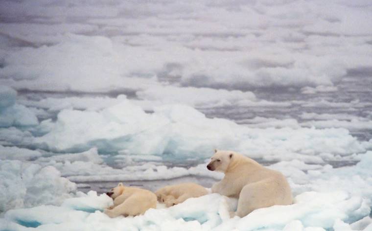

Fig. 18. An example of application of the method to the image of medium contrast [8]: a – the original image, b – application of the method described in this paper
|
|
|
|
b) |
|
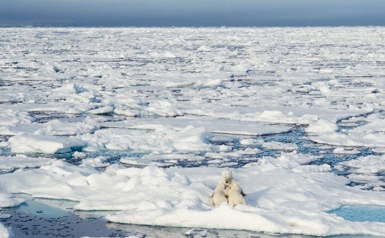

Fig. 19. An example of application of the method to the high-contrast images [8]: a – the original image, b – application of the method described in this paper
|
a) |
|
|
b) |
|
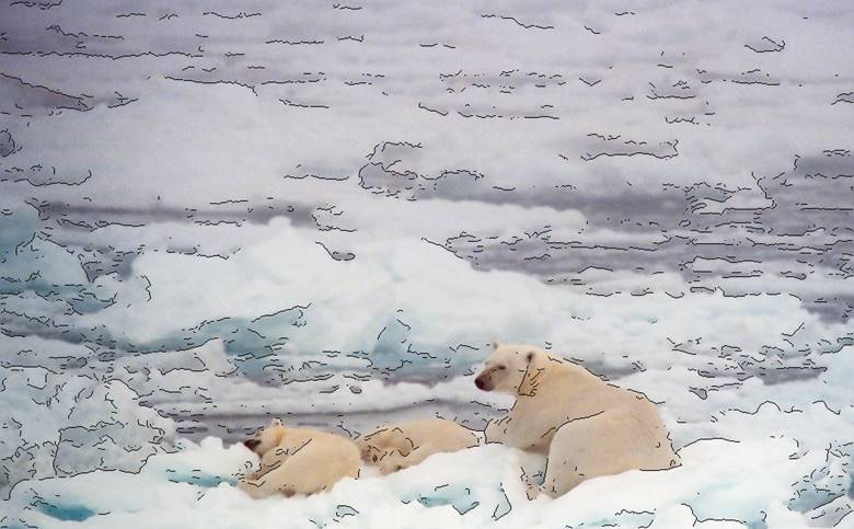
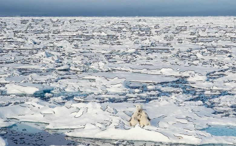
Fig. 20. Founded low contrast edges for images: a –from Figure 18a, b –from Figure 19a
Fig. 21. Video: “submarine” [4]
Fig. 22. Video: “bears” [8]
5. Conclusion
The main difference of the developed method is that it detects and underlines low-contrast bounds. The major part of the image remains untouched while the applied changes are visible only on low-contrast images. Area of use: underwater, foggy or smoky images, results of the nighttime photography, pictures of homogeneous snowy landscapes.
The developed method was tested on images of varying contrasts. The results of applying the proposed method are clearly visible on low-contrast image (Figure 17) and virtually invisible on the high-contrast image (Figure 19), despite the large number of low-contrast edges found (Figure 20b).
Processing time per frame (1013 × 628) on a processor with a frequency of 3 GHz was is ≈ 5 sec. The processing time of the same frame portion (320 × 200) was ≈ 0.5 sec. The most computationally expensive operations are skeletonization of the binarized gradient image and the operation of construction of bounds by the Canny method. Since these operations do not require conveyor processing and can be performed simultaneously, the running time, by using parallel computation can be significantly reduced.
Future work on this topic addresses the development of the program that will use an algorithm enabling frame by frame processing by the means of OpenCV library. On the evidence from existing experience in stream video processing [9] it is suggested that the time per frame ratio will decrease.
The developed algorithm is intended to be used in the computer vision system of the universal collective rescue vehicle with rotary screw, designed for evacuation in emergencies and reduction of the effects of man-made disasters in the Russian Arctic shelf.
Acknowlegment
This work was carried out at the NNSTU named after R.E. Alekseev, with financial support from the government in the face of the Russian Ministry of Education under the Federal Program "Research and development on priority directions of the scientific-technological complex of Russia for 2014-2020", the unique identifier of the project: RFMEFI57414X0055.
References
[1] Nicholskaya O. Psychology. Textbook: Tomsk State Pedagogical University, Information on http://koi.tspu.ru/koi_books/nikolskaya4/vv.htm
[2] Serge Scout Features of human color perception. Computerra Vol. 45 from 17 November 1998.
[3] Information on http://robocraft.ru/blog/computervision/484.html (Treatment date December 10, 2014)
[4] Film frames from "The Magic of the Big Blue. Seven Continents, 7th Series, Poland, directed by: Dariusz Sepiolo Dariusz Sepiolo (Best Film Co), 2011
[5] http://idea2.ru/blog/idea2ru/845.html (Treatment date March 11, 2015)
[6] Gruzman I.S., Kirichuk V.S., Kosykh V.P., Peretyagin G.I, Spector A.A. Digital image processing in information systems: Textbook. – Novosibirsk NSTU (2002). p. 352
[7] https://ru.wikipedia.org/wiki/Оператор_Кэнни (Treatment date February 08, 2015)
[8] Film frame from "To the Arctic", IMAX Film studio, 2012
[9] Babakina NA, Kolesnikov MP. The Construction of Dynamic Geometric Patterns of Environment for Mobile Autonomous Systems // Modelling of Systems and Processes. 2012. №1. p. 51-58.