THE APPLICATION LOGICAL AND VISUAL PROGRAMMING INTERFACE FOR IMAGE ANALYSIS OF THE GEOMETRIC BODIES
N.G. Volchenkov
National Research Nuclear University MEPhI (Moscow Engineering Physics Institute)
Contents
1. Theoretical basis of using logical programming for image processing
1.1 DCG - the syntactic analysis mechanism in logical programming
1.2 Using the mechanisms Pattern matching and Backtracking
2. The technology of implementation and the obtained results
2.1 The steps of preprocessing of an image
2.2 The step of structural analysis of an image
2.3 The step of postprocessing
3. The state registration of the program
Annotation
Logical programming (in particular, the Prolog language) can be used for the analysis of the images, for which the descriptions can be built easily in the form of the texts in the languages that can be syntactically analyzed. For emphasizing the expressiveness of the initial data and results of such analysis it is advisable that any visual language of programming, for example, Visual Basic should be used “to help” Prolog. The result of syntactic analysis can be not only the list of separate bodies on the image, but also their coordinates, sizes, color. These data can be useful, for example, for a robot-manipulator. As an example of a category of the bodies, the images of which can be analyzed that way, here we take the geometric solids in the form of the prisms and cylinders painted in the local colors with the cuts and the openings. In the work the examples of initial scanning images are given as well as their intermediate vector idea and obtained result - lists of the revealed solids with the characteristics indicated.
The key words: structural (syntactic) methods of the image analysis, structural description of the image, scanning image, vector idea, polygon, logic programming, the Prolog language, visual programming, the Visual Basic language
Preface
An industrial robot-manipulator can face an “intellectual” challenge to analyze the image with a block of different objects in its field of vision, to separate the necessary object, evaluate its size and location in connection to other objects in order to plan its actions for capturing and moving the object. To solve this problem the robot can obtain only the scanning image from the video camera. In Figure 1 there are the examples of such images.
|
а) |
b) |
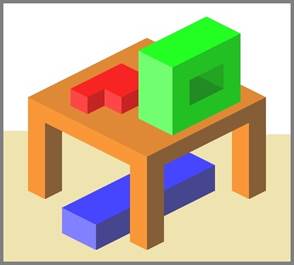
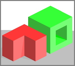
Fig. 1. The examples of scanning images а) 4 objects и b) 2 objects
As a result of the analysis the following questions should be answered:
· How many objects does the image contain?
· What are the size and color of every image?
· What are the coordinates of the gravity centre of every image?
In prospect another question may be raised: what is the mutual arrangement of the solids? (It can be important in case the robot will have to solve the problem of releasing the captured object.)
Among the different approaches to the programming of the analysis of the image syntactic (structural, morphological) analysis on the base of logic programming can be used to answer the above mentioned questions. [1, 2, 3, 4].
Why was this approach chosen? There are other ones beside the syntactic one. For example, those, that are based on the neuron networks, discriminant etc.
To justify this choice we’d like to mention that the author of this article has been giving lectures on “Logical Programming. The Prolog Language” course to the students of the department of Cybernetics National Research Nuclear University MEPhI for many years. The main aim for studying the course is to get students acquainted to nonconventional paradigm of declarative programming [5] which completely differs from the traditional one, the paradigm of imperative programming.
Though the languages of declarative programming (like Prolog, in particular) are algorithmically full, their main purpose is not solving computational, but symbol processing tasks which are the characteristic for the AIS – (Artificial Intelligence Systems) [1, 4]. The most typical solution of those tasks is using of heuristic algorithms which demands specific mechanisms. They include:
· pattern (complex data structures) matching;
· backtracking – solver automatic return in case of a clinch;
· recursive technique of programming.
We presume that wide application of these instruments makes it possible to call declarative programming the language of artificial intelligence.
Since one of the topics of the course “Logical Programming” is “The Using Prolog Algorithms for Solving Tasks of the Artificial Intelligence” the abovementioned task of the analysis of geometrical solids can be a very typical example of solving tasks in the class. That’s why the obtained results in creating of a demonstration prototype of the “intellectual” component of the geometrical solids analysis system [9, 10] may help students with mastering the most important skill of the course – the application of the declarative approach in programming of the artificial intelligence.
The long-term experience of usage the languages of functional and logical programming for solving the symbol processing tasks showed the necessity of visualization of the solutions of the practical tasks of the type. It is very difficult to interpret the results without visualization.
The above given example of the image analysis illustrates the necessity, as it was shown in the article. To visualize we offer the two programming languages interface – the language of logical programming (Prolog) and the visual imperative language (Visual Basic), or to be more exact, two programming systems for these languages [7, 8]. Prolog is used for solving the main, “intellectual” part of a task. Visual Basic – for the calculations additional to the logical inference and for creating a visual image of the inference.
1. Theoretical basis of using logical programming for image processing
Logical programming [5, 6] is useful for image recognition (here, for the recognition and analysis of the images belonging to quite numerous and widespread classes) in case when those images are quite complicated and their recognition demands considering a lot of characteristics. In addition the traditional approach to solving recognition tasks (so called discriminant approach, based on dividing the attribute space into the areas and ranging the attributes into the areas) is not very efficient. (Note that later in the article the term image will be replaced on picture).
The main feature of the images of the abovementioned classes is that they can be interpreted as hierarchic tree like structures where the image of the whole picture is the root of a downward directed tree. The daughter nodes of the root are the simpler subimages of which it consists. The daughter vertexes of those subimages are even much simpler subimages and so on. The dangling vertexes of the tree are the so called primitives – the indivisible units. To describe them simple symbol structures (of the type f(x1, …, xn)) can be used: Let’s call them terminal symbols. The whole picture can be written as character strings consisting only of terminal symbols and operational signs between them that represent bonding techniques of the primitives. As a rule, the description of the images of the above mentioned classes can give us such character strings after some simple transformations.
Example 1.1. Terminal symbols for the primitives (Figure 2, a), the depiction of the letter “A” (Figure 2, b) and its text representation – the character strings (Figure 2, c)
|
|
|
|
|
a) |
b) |
c) |
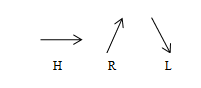
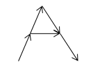
Fig. 2. The primitives (a); depiction consisting of these elements (b) and a character string (c)
In this example the binary operators of concatenation of the primitives in the Picture Description Language created by Alan Shaw [11]. Every primitive is marked with two points: a head and a tail point. Only two operators were used here: + and *. The content of these operators is the following:
· “a + b” – the head point a joins the tail point b, the tail point a becomes the tail result point; the head point b becomes the head result point;
· “a * b” – the head point a joins the head point b and the tail point a joins the tail point b. Their head and tail points become the head and the tail result points.
1.1 DCG - the syntactic analysis mechanism in logical programming
The most vivid and effective way to obtain results while structural (syntactic) recognition and image analysis (pictures, in particular) is to use formal grammar for generation of the abovementioned hierarchic structures. A character string corresponding the primitives of which an image to be analyzed consists as well as the operators – like the ones that are demonstrated in Example 1.1. – is considered to be the text of the formal language. This language defines the class of the images. The image is considered “recognized” if it is proven that the text describing it belongs to the language.
The following foursome is called the generative grammar:
G = <VT, VN, S, P>,
where VT, VN – terminal and nonterminal vocabularies consequently,
S – the initial symbol, P = {ai ® bi} – the set of inference rules, where ai – a string containing a nonterminal symbol, bi – an arbitrary string of terminal and nonterminal symbols.
The ratio l Þ m is called the genuine generation,
where l = d1 ai d2, m = d1 bi d2 and with the rule: ai → bi.
The following ratio g Þ* gn, n = 1, 2, ... is called the generation,
if there is a ratio order g Þ g1 Þ ... Þ gn.
The following set is called the language generated with grammar G:
L(G) = {g | S Þ* g}
(set of terminal strings g – the strings consisting only of characters from the terminal vocabulary VT).
Grammars and languages are divided into types. In practice the most often used are the grammars and languages of the following three types:
Types of grammars:
- If a nonterminal symbol in the left part of any grammar rule is surrounded with other symbols (terminal and\or nonterminal) the grammar is called the context-dependent grammar.
- A grammar can be called the context-free one if the left part of every inference rule of it is a string consisting of the only one nonterminal symbol.
- A context-free grammar is called the automaton grammar if every inference rule is of the form of:
А ® а В or А ® а or А ® l,
where A, B are nonterminal symbols and a is a terminal symbol, λ is an empty string.
Types of the languages:
- A language is called the finite-state language if an automaton grammar may be used for its generating. (Undoubtedly, other types of grammar can be used for it.)
- A language is called the context-free language if a context-free grammar is used for generating it, but the automaton grammar cannot be used for it.
- A language is called the context-dependent if the context-free grammar cannot be used for generating it.
A special mechanism is built in Prolog making it possible to build effective top-down parser for the languages defined formal grammars of different types. It’s DCG – Definite Clause Grammar – mechanism. If available it makes it possible to create effectively working downward grammar sniffer in Prolog. The main advantage of using the abovementioned mechanism for image recognition and analysis is a widespread using of recursive rules in generative grammars and in DCG sublanguage in particular. Their absence would make the task of recognition of images with a great number of regular solid combinations a problematic one.
Example 1.2. The depiction of the set of solids (pyramid of cubes) with a regular fragment is shown in Figure 3. Further there is a grammar with recursive rules generating the description of the class of the images of that type with an arbitrary number of repetitions.
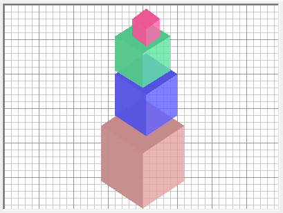
Fig. 3. The image with a regular fragment (pyramid of cubes).
Pir à Cube | DCube + Sub + Pir
Cube à LSide * HSide * RSide
DCube à LSide * HPSide * SR
LSide à ( s + nw + n + so )
RSide à ( no + s + sw + n )
HSide à ( nw + no + so + sw )
HPSide à ( nw + no + so + sw ) | ( nw + no + s + so + no + so + sw ) | ( nw + no + so + no + n + so + sw ) | ( nw + no + s + so + no + n + so + sw )
Sub à nw | n | no
Here we’ve used the same two operators (+ and *) in the PDL language as in the Example 1.1. In according to their semantics points t and h for the image of every cube are exactly at the junction point of the three of its visible planes.
There is no need to explain the meaning of the eight primitives (arrows): they are cardinal directions – n – nord, no – nord-ost etc.
Nonterminal symbol Sub corresponds the virtual invisible element. It points out that the subsequent cube DCube (counting from the bottom) with a “shut” upper plane HPSide is under the pyramid Pir. Nonterminal Cube means a cube with a clear upper plane – it’s the top of the pyramid.
1.2 Using the mechanisms Pattern matching and Backtracking
For solving the task of the image analysis of the set of geometrical solids described in this article the author managed to exclude the necessity of Prolog programming mechanism of syntactic analysis by using the DCG sublanguage. The wide possibilities of such mechanisms as Pattern matching and Backtracking in logical programming were used instead.
More specifically:
- Pattern matching with great variety of samples is well-developed in Prolog. It makes it possible to hypothesize about different primitives in image descriptions. For example, one of the four variants may be a property of a vertical section in an outline drawing, as it will be shown in the next unit of the article: (1) a convex face out of two flat faces of the body, (2) a concave face out of two flat faces of the body; (3) a vertical line between the solid and the right background; (4) a vertical line between the solid and the left background. Choosing one of this variants can restrict the number of them for another edge etc.
- Backtracking starts working (with no need in programming!) if choosing any variant leads to a failure. The analyzer used in Prolog will be back to the choice point and the analysis will be continued.
2. The technology of implementation and the obtained results
While the implementation of the prototype of the demonstrational system of the solids image analysis which was described in this article, the process of analysis was divided into some steps that will be thoroughly described in this unit. They are:
- three stages of preprocessing;
- the step of the structural analysis of the image;
- the postprocessing.
(It should be mentioned that the first results obtained while working at the prototype of the demonstrational programming system were given in our article in 2010 [10].)
2.1 The steps of preprocessing of an image
Preprocessing of an image is its transformation into the form suitable for the application of the method of structural analysis. It consists of 3 steps.
Step 1. By means of scanning the image all the cross-points are marked out – the top points of homogeneously colored connected fields – “polygons”. It’s necessary to make the list of the point pairs – polygon sections – and calculate the average color of each polygon.
Step 2. The transformation of scanning image into the vector one, consisting of: (1) set of descriptions and (2) the list of all the top points.
It’s demonstrated in the example:
Example 2.1. Let’s look at the vector image obtained after the processing of the scanning image shown in Figure 1, b)
The number of every polygon out of ten is given under one of its top points.
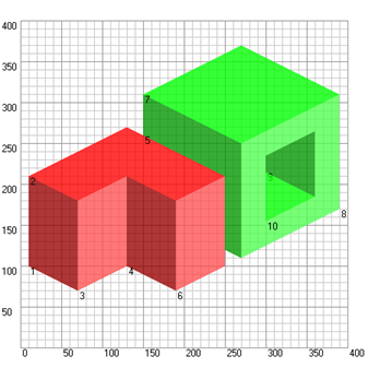
Fig. 4. The example of a vector image made after the processing of a scanning image shown in Figure 1, b)
The vector image shown in Fig. 4, may be introduced in the following two lists:
· The list of polygons in the form: p(<a>,<r>,<g>,<b>) [< top points number list>]:
p(200,150,000,000) [1,2,3,4]
p(200,255,000,000) [2,5,6,7,8,9,3]
p(200,255,080,080) [4,3,9,10]
p(200,150,000,000) [10,9,8,11]
p(200,000,150,000) [6,12,13,14,15,7]
p(200,255,080,080) [11,8,7,15,16]
p(200,000,255,000) [12,17,18,13]
p(200,080,255,080) [19,14,13,18,19,20,21,22,23,24,20]
p(200,000,150,000) [23,22,21,20]
p(200,000,255,000) [24,23,20]
· Top points list in the form: n(<x>, <y>):
|
n(010,100) n(010,210) n(070,180) n(070,070) n(130,270) n(150,260)
|
n(250,210) n(190,180) n(130,210) n(130,100) n(190,070) n(150,310)
|
n(270,250) n(270,110) n(250,120) n(250,100) n(270,370) n(390,310)
|
n(390,170) n(360,185) n(360,265) n(300,235) n(300,215) n(300,155)
|
Step 3. Regarding the polygons sections the edges of some solids, the sample description is set for each section. The description is introduced in the form of a structure f(a1, a2, a3) with the three arguments of the Prolog language [3, 4, 5].
Structure f function is the type of the edge: vr, pr or nr. The vertical, ascending or descending to the right as shown in Figure 5 – а), b), c).
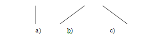
Fig. 5. Three types of the edges for this class of the images
Arguments a1 and a2 of the structure are either constant fon or the characteristics of the left and right planes consequently. For example: left_plane:solid1, right_plane:solid2.
Argument a3of the structure - the plane property – is one of the four values: up (upwards), down (downwards), posit (gibbose), negat (concave). The first two of them are for the edges on the holding line on condition that a polygon is moved around clockwise. The latter two are, consequently, for the edges of the gibbose and concave planes of a solid.
For example, the 1st section of the 1st polygon of the above given example is a vertical edge with the description:
vr (fon, left_plane:solid1, up);
and the 2nd section of the 1st polygon and the 7th section of the 2nd polygon in the above given example are the same edge with the following description:
nr(left_plane:solid1,upper_edge:solid1, positive).
It goes without saying that at this stage of the image preprocessing the task of getting the above mentioned descriptions is not to be solved. It is for the later, more “intellectual” stage. But here only the structures “patterns” are prepared, which must be compared with the above mentioned ones. All the three arguments in the “patterns” are variables (as far as Prolog concerned), which can take different values. For example, the following structures will be built at the stage of preprocessing for the above given descriptions of the edges:
vr(fon, R1, E1), nr(R1, R2,E2).
The complete list of such structures for the image shown in Figure 4, which is made at this stage contains the following elements:
|
vr(fon,R01,E01), nr(R01,R02,E02), vr(R01,R03,E03), nr(fon,R01,E04), pr(fon,R02,E05), nr(R02,fon,E06), nr(R02,R05,E07), pr(R02,R06,E08),
|
nr(R04,R02,E09), pr(R02,R03,E10), vr(R03,R04,E14), pr(R03,fon,E15), vr(R04,R06,E18), nr(fon,R04,E19), vr(fon,R05,E20), nr(R05,R07,E21),
|
vr(R05,R08,E22), nr(fon,R05,E23), vr(R06,R05,E24), vr(R06,fon,E29), pr(R06,fon,E30), pr(fon,R07,E31), nr(R07,fon,E32), pr(R07,R08,E33),
|
pr(R08,fon,E35), vr(R08,fon,E38), vr(R09,R08,E40), pr(R08,R09,E41), vr(R08,R09,E42), vr(R08,R10,E43), pr(R10,R08,E44), nr(R10,R09,E49).
|
(The list was completed after the uniting of description-duplicates of the same edges, got during the analysis of different polygons.)
2.2 The step of structural analysis of an image
Step 4. The procedure of analysis, based on the comparing of the samples, which was worked out in Prolog, is applied to the obtained quantity of descriptions. The idea belongs to D.H.D.Warren, 1977) [2]. The logical programme contains the definitions of the variety of the samples compared to the ones obtained at the Stage 2.
Сonventionally speaking we can call the complex of the above mentioned definitions of Prolog a grammar, by means of which the analysis of the images of the class is realized. (Syntactic approach to the pattern recognition was expanded quite fully in the literature, in the monograph by King Fu [6].) Such Grammar was suggested by Warren for the ordinary images of several solids with flat planes. It consists only of 12 sample statements in the form of Prolog facts:
vr(left:B, right:B, posit).
vr(right:B1, left:B2, negat).
vr(right:B, X, down).
vr(X, left:B, up).
pr(horizontal:B, right:B, posit).
pr(right:B1, horizontal:B2, negat).
pr(X, horizontal:B, up).
pr(right:B, X, down).
nr(left:B, horizontal:B, posit).
nr(horizontal:B1, левая:B2, negat).
nr(horizontal:B, X, down).
nr(X, left:B, up).
For the uniting of the variables of the same names all the descriptions of the edges of the analyzed text (image descriptions) must be included into one Prolog goal. For that purpose Warren suggested representing the list of arcs as the right part of the only Prolog rule.
For example:
solution(R01;R02;R03;R04;R05;R06;R07;R08;R09;R10) :-
vr(fon,R01,E01), nr(R01,R02,E02),
vr(R01,R03,E03), nr(fon,R01,E04),
pr(fon,R02,E05), nr(R02,fon,E06),
nr(R02,R05,E07), pr(R02,R06,E08),
nr(R04,R02,E09), pr(R02,R03,E10),
vr(R03,R04,E14), pr(R03,fon,E15),
vr(R04,R06,E18), nr(fon,R04,E19),
vr(fon,R05,E20), nr(R05,R07,E21),
vr(R05,R08,E22), nr(fon,R05,E23),
vr(R06,R05,E24), vr(R06,fon,E29),
pr(R06,fon,E30), pr(fon,R07,E31),
nr(R07,fon,E32), pr(R07,R08,E33),
pr(R08,fon,E35), vr(R08,fon,E38),
vr(R09,R08,E40), pr(R08,R09,E41),
vr(R08,R09,E42), vr(R08,R10,E43),
pr(R10,R08,E44), nr(R10,R09,E49).
The author made Warren Grammar applied to the wider range of solids. Beside the prisms similar to the ones that shown in Figure 1, cylinders are also considered. Moreover, horizontal surfaces can be upper and lower. In order not to enlarge the number of primitives (Figure 5) the author suggests substitute the arcs of ellipses for their patch-linear approximation, which can be very rough – for example, as shown in Figure 4. The number of sample statements is enlarged in this case from 12 to 48:
|
vr(left:B, right:B, posit). vr(right:B1, left:B2, negat). vr(right:B, X, down). vr(X, left:B, up). vr(vert_cyl:B, X, down). vr(X, vert_cyl:B, up). pr(:B, right:B, posit). pr(left:B, lower:B, posit). pr(right:B1, upper:B2, negat). pr(lower:B1, left:B2, negat). pr(upper:B, vert_cyl:B, posit). pr(X, upper:B, up). pr(X, left:B, up). pr(right:B, X, down). pr(left:B, X, down). pr(left:B,right_cyl:B, posit). pr(left_cyl:B, right:B, posit). pr(right_cyl:B, X, down). pr(X, right_cyl:B, up). pr(X, left_cyl:B, up). pr(right:B1, left_cyl:B2, up). pr(right_cyl:B1, left:B2, down). pr(lower:B, X, down). pr(vert_cyl:B, X, down). |
pr(X, vert_cyl:B, up). pr(vert_cyl:B, upper:B, down). pr(lower:B, vert_cyl:B, up). nr(left:B, upper:B, posit). nr(lower:B, right:B, posit). nr(upper:B1, left:B2, negat). nr(right:B1, lower:B2, negat). nr(vert_cyl:B, upper:B, posit). nr(upper:B, X, down). nr(right:B, X, down). nr(X, left:B, up). nr(X, right:B, up). nr(left_cyl:B, right:B, posit). nr(left:B, right_cyl:B, posit). nr(X, left_cyl:B, up). nr(left_cyl:B, X, down). nr(right_cyl:B, X, down). nr(right_cyl:B1, left:B2, down). nr(right:B1, left_cyl:B2, up). nr(X, lower:B, up). nr(X, vert_cyl:B, up). nr(vert_cyl:B, X, down). nr(upper:B, vert_cyl:B, up). nr(vert_cyl:B, lower:B, down) |
|
|
|
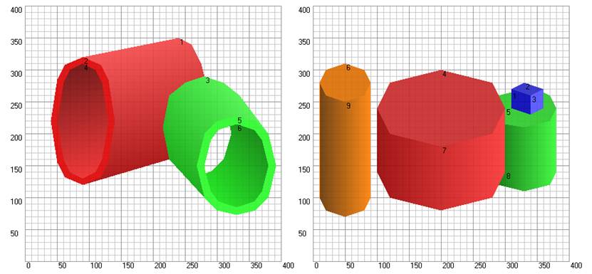
Fig. 6. Examples of the images with the “approximated” cylinder surfaces
The mechanism of effective scanning contained in Prolog makes it possible to obtain the only variant of collating: to define the planes (surfaces) of the particular solids particularly oriented (upper, lower, right, left, various cylinders) – the values of the variables R1, R2, … as well as defining the properties of the edges – the values of the variables E1, E2, …
In the above given example (Figure 4) the collating brings about the only result. Here are the results only for the first and the last three edges:
vr(fon,R01,E01) ↔ vr(fon, left_plane:solid1, up),
nr(R01,R02,E02) ↔ nr(left_plane:solid1, upper_plane:solid1, posit),
vr(R01,R03,E03) ↔ vr(left_plane:solid1, right_plane:solid1, posit),
…
vr(R08,R10,E43) ↔ vr(right_plane:solid2, upper_plane:solid2, down),
pr(R10,R08,E44) ↔ pr(upper_plane:solid2, right_plane:solid2, posit),
nr(R10,R09,E49) ↔ nr(upper_plane:solid2, left_plane:solid2, negat).
The above given result is easy to generalize by means of enumeration of all polygons of the image and defining the body they belong to. For the above given example the following list is the generalized result.
|
R01:[01, left_plane]. R02:[01, upper_plane]. R03:[01, right_plane]. R04:[01, left_plane]. R05:[02, left_plane]. |
R06:[01, right_plane]. R07:[02, upper_plane]. R08:[02, right_plane]. R09:[02, left_plane]. R10:[02, upper_plane]. |
2.3 The step of postprocessing
The evaluating of the solids sizes and colours takes place at the 5th, final, stage.
Step 5. The solids sizes are evaluated as some average characteristics of the square areas of the visible planes (surfaces) as well as the coordinates of their “conventional centres of gravity”. Should any uncertainty arise (varying interpretation of some disunited parts of a solid as some separate parts) it may be eliminated by means of analysis of the colour of these parts. The colour of each solid is set as an average colour of all its planes (surfaces). The correlation of values of the colour components (R, G and B) makes it possible to define the value of the linguistic variable “colour” for every defined solid. For instance, the generalized result of the analysis of the image given in Figure 2 is the following:
Solid 01 : (132, 155) : 054 : c(200, 213, 032, 032) : red
Solid 02 : (296, 227) : 086 : c(200, 016, 213, 016) : green
Prototypal system of analysis of the source image implies, firstly, the restriction on the class of the details should be restricted on the objects with flat, uniformly dyed planes and cylindrical surfaces and, secondly, the step of preprocessing (steps 1 and 2) is completed: there is a vector idea in the form of a text file with the description of the combination of coloured polygons. There are other restrictions, but they are minor.
The main advantage of the suggested system of image analysis prototype is a well-functioning interface of the main application written in a language of imperative type (here, in Visual Basic) – these are steps 3, 5 of the above described process – as well as the called programme in the language of the declarative type Prolog (step 4). The difference of the paradigms of these languages, described in the 1st chapter of the book [4] and in the article [5], is of principal importance here, at the given stages: it is easier and more convenient to program engineering challenges of arithmetic calculations in Basic; but an enumerating “intellectual” task of the analysis – in Prolog.
More specifically, the framework by Microsoft Visual Studio 2010 and the language Visual Basic 2010 [8], based on Microsoft .NET Framework 4 are used at steps 3 and 5. But at Step 4, solving the main “intellectual” task, LPA-Prolog [7] and the so called base Prolog dialect with a multitude of built-in predicates are used.
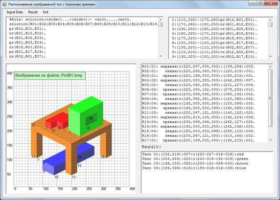
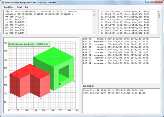
The examples of the results – the screenshots of the demonstrated Windows application with the images and the lists of the defined solids and their characteristics – are shown in Figure 7 – а) and Figure 7 – b).
а)
b)
Fig. 7. The examples of screenshots of the application where the interface Visual Basic 2010 – Prolog LPA is realized, with the results of the image analysis shown in Figure1 (а and b).
The simulation of the steps 1-3 (preparation of the vector idea) is made with the use of the application also created in Visual Basic 2010 [8], which may be updated in the later versions of the language, required the platform Microsoft .NET Framework 4 (4.5, 4.5.1 etc.).
3. The state registration of the program
The result given in the article is officially registered: the author has got a State Registration Certificate for the ECM program “The Demonstrational Programme of image analysis of the solids with flat faces.” № 2015611531 (the date of the registration – 30th January 2015) [9].
Conclusion
A potential possibility of combination of means of logical (structural) approach to the image recognition and analysis with the visual programming features is considered. In particular, the problem of structural (syntactic) recognition of the solid images which makes it possible to bind the separate image fragments to the certain solid. Visualization is of utter importance for this task. It obviously demonstrates the obtained results: separate solids of the image defined by a logical programme, their characteristics and, in prospect, the mutual configuration of the solids required by a robot-manipulator for solving various tasks of capturing and moving them.
The practical result has been obtained: a demonstrational program for the students studying logical programming was written and verified on different examples. That program is a prototype of the system of the image analysis of some solids. It was officially registered and copyrightable with the State Registration Certificate for the ECM program.
List of References
1. Bratko, Ivan. PROLOG Programming for Artificial Intelligence, Third edition. Addison-Wesley. 2000.
2. Warren, D.H.D. PROLOG – the language and its implementation. / Warren D.H.D., Pereira L.M., Pereira F. Proceedings of the Symposium on Artificial Intelligence. SIGPLAN Notes, 12(8), 1977.
3. Volchenkov, N.G. Logicheskoe programmirovanie. Jazyk Prolog [Logic programming. Prolog language]. – M.: Publishing Center National Research Nuclear University “MEPhI”. 2015. [In Russian]
4. Sergievsky, G.M. Funkcional'noe i logicheskoe programmirovanie [Functional and Logic Programming] / G.M. Sergievsky, N.G. Volchenkov. – M.: Publishing Center “Academia”. 2010. [In Russian]
5. Volchenkov, N.G. Ispol'zovanie sovremennyh informacionnyh tehnologij v obuchenii studentov po napravleniju «Informatika i vychislitel'naja tehnika», razlichnym paradigmam programmirovanija: «Sovremennye nauchnye issledovanija i innovacii». [The use of the modern information technologies in the teaching students specializing in "Computer Science", various programming paradigms. Scientific & practical journal «Modern scientific researches and innovations»]. 2015. № 3. [electronic resource]. URL: http://web.snauka.ru/issues/2015/03/47345 (access date: 10.05.2015). [In Russian]
6. Fu, K.S. Strukturnye metody v raspoznavanii obrazov [Syntactic Methods in Pattern Recognition] / K.Fu. – Academic Press, New York and London, 1974. [In Russian]
7. Logic Programming Associates Ltd. [electronic resource]. URL: http://www.lpa.co.uk/ (access date 21.03.2015).
8. Ziborov, V.V . Visual Basic 2010 na primerah [Visual Basic 2010 examples] / Viktor Ziborov. – S-Pb. BHV-Petersburg, 2010. [In Russian]
9. Certificate of state registration № 2015611531 "Demonstration program on the analysis of images of bodies with flat faces." Author: Volchenkov N.G. (RU). [electronic resource]. URL: http://www1.fips.ru/Archive/EVM/2015/2015.02.20/DOC/RUNW/000/002/015/611/531/document.pdf (access date 07.04.2015).
10. Volchenkov, N.G. Sintaksicheskij analiz izobrazhenij sovokupnosti tel nekotorogo klassa, ispol'zujushhij interfejs logicheskogo i imperativnogo vizual'nogo jazykov programmirovanija [Parsing images of geometrical bodies using interface logical and visual programming languages] / N.G. Volchenkov. – M.: “New Information Technologies”, FSUE "TSNILOT", 2010, № 1. [In Russian]
11. Shaw, A.C. A formal picture description scheme as a basis for picture processing system. Information and Control. 1969, v.14.