AUTONOMOUS NAVIGATION OF DRONE BY ONBOARD VIDEO CAMERA: ALGORITHM AND COMPUTER MODELING
B.A. Zalesky1, V.B. Shuvalov2
1United Institute of Informatics Problems of National Academy of Sciences, Minsk, Belarus
2National Research Nuclear University MEPhI (Moscow Engineering Physics Institute), Moscow, Russian Federation
zalesky@bas-net.by, vbshuvalov@yandex.ru
Content
2. Algorithm of navigation UAV and returning it to starting point of its route
Abstract
The algorithm of autonomous navigation of an unmanned aerial vehicle (UAV) equipped with an autopilot, onboard inertial navigation system, onboard computer and one video camera, preferably mounted on a gyro platform, is proposed. It is designed to return the autonomously flying UAV to the starting point of its route without the use of external navigation signals such as GPS or GLONASS. The idea of the algorithm consists in comparison each of the current frame, made by the onboard camcorder during UAV return home, with frames shot by the camcorder while the apparatus flight from the starting point along a predetermined path.
The offered algorithm can also provide autonomous navigation of the unit without use of external navigation signals throughout the flight. For this it needs a pre-stored video sequence, or a sequence of pictures, for example, satellite imagery, completely covering any realized route of the apparatus from the starting point to the destination point, and suitable for solving the problem of recognition.
Results of computer modeling of the autonomous navigation process and its visualization are presented. Simulation of the UAV flight has been done, first, based on videosequences made by smartphones, and then with help of movies captured by the onboard camcorder of the quadcopter DJI Fantom 3 Professional.
Computational experiments have shown robustness and sufficient accuracy of the offered algorithm.
Keywords: UAV, autonomously flying, navigation, onboard video camera
1. Introduction
Problems of navigation of UAV have become especially urgent in recent years due to the rapidly increased number of drones of various types used for different purposes. Autonomous navigation of small and medium-sized UAV is particularly important in our days. The types of devices that are extensively exploited, have relatively primitive inertial navigation systems, not able to provide flight along a given trajectory without exploiting signals from satellites or other external systems. In the absence of external navigation signals such devices estimate their position with large errors, and as consequence, they fly in the wrong direction being from time to time lost forever.
In recent years, onboard inertial navigation systems include video cameras and that have increased essentially accuracy of estimation of drone position (as well as velocity and acceleration). Precision of drone navigation have grown, but the problem of autonomously flying drones return has not yet been completely solved [1-3]. The great progress here was achieved for vehicles equipped with one video camera, a rangefinder and a GPS navigator, or with two video cameras and an altimeter. The use of external navigation signals greatly facilitated navigation and increased its accuracy. Now on-board navigation systems, equipped with GLONASS / GPS receivers, provide reliable flight of the UAV in autonomous mode in the presence of the signals.
A several solutions of the formulated problem returning home of small UAVs with the help of two on-board cameras, without use of the navigation signal are actually versions of the sophisticated algorithm SLAM [4-6]. One of the most important steps of that algorithm consists in estimation of the 3D scene, captured with on-board camcorders, by means of matching key-points (which are centers of local regions, such as, object corners or color blobs differing from the surrounding background image), found in the pair of current video-frames. After that, the 3D scene estimate is applied to evaluate the drone location. However, the SLAM is intended for indoor navigation or navigation of vehicles flying at low altitudes in urban environments. In the case of long distance flights, exploitation of the algorithm is a difficult task since it operates with ordered sets of key-points and, besides, estimations of the 3D scene become incorrect at high altitudes.
Let us formulate the problem in general form without mentioning technical details. Assume that the drone is equipped with an autopilot, an onboard computer and a camcorder mounted on a gyro platform, which provides strictly vertical orientation of the camera optical axis. Suppose also that the drone successfully flew from the starting point along a predetermined route, possibly, by means of external (may be, satellite) navigation signals. During the flight, the computer stored in its memory overlapping images of the landscape, shot by the onboard camera. In some instant, the external navigation signals were lost, so the drone navigation system cannot evaluate coordinates of the vehicle with the required accuracy.
The task is to ensure returning of the UAV to the starting point of its route without use of external navigation signals.
To facilitate the formulation of the problem, let us suppose that at time of loosing of external navigation signals the drone was located over a point of the landscape presented in one of the last frames shot by the onboard camera. This situation is quite real, for instance, for quadcopters. Otherwise, steps implementing search in the supplied frame collection of a picture, containing image of the terrain area, which is currently under the drone, should be included in the algorithm. The task of such area search is a topic of separate discussion.
The algorithm solving the formulated problem of drone return to the starting point of its route is presented. It finds the location of the drone in one of the frames, made on the way from the starting point, by matching part of the current image, which is under the UAV, to those frames. Then it uses the found correspondence for determining part of the return route. The algorithm does not need to work with a geographical or some another stationary coordinate systems. It computes the displacement vector of the returning drone with help of the found correspondence. The displacement vector is set, for instance, as the affine transformed vector that begins at the point of location of the drone in the correspondent supplied frame and ends at the frame center (see Fig.2). The affine transformation is calculated explicitly by the focal distance of the camera and the drone altitude.
Description of a computer model, simulating the drone return flight, and results of computer experiments are also done.
Although, the algorithm is intended for navigation of airplane UAVs and quadcopters, for the sake of clarity, we can imaging only the problem of quadcopter navigation, because from our point of view, control of quadcopters is easier than control of an airplane UAV. Immediately after losing external signals they can hang motionless or start moving in the opposite direction without performing loop that are necessary for airplane UAVs.
It is now possible to buy several models of quadcopters that satisfy the formulated requirements (for instance, DJI Fantom 3 Professional weighting 1280 grams, which is shown at Fig.1). The Fantom 3 Professional is equipped with the autopilot having the altimeter (and of course, other sensors), the onboard camcorder mounted on the gyro platform, the control channel. The camcorder shoots video of sizes from 1280x720 px to 4096x2160 px with framerates from 24 fps to 60 fps. The equipment mounted on this quadcopter possesses almost all devices, which make possible solving the formulated task of the quadcopter homecoming without of external navigation signals. Only onboard computer is absent, but smartphone processors can be taken as such the device.
2. Algorithm of navigation UAV and returning it to starting point of its route
As mentioned in the introduction, we consider the problem of navigation of a drone by the combined use of the onboard inertial navigation system and the camcorder mounted on the gyro platform, which ensures strictly vertical orientation of the optical axis of the camera. In the general case, the presence of the platform is not necessary, but it is preferable, since the gyro platform improves significantly navigation accuracy and the task solution. To simplify the description of the algorithm, we assume that our drone is the quadcopter that can quickly change the flight trajectory and move in any direction without additional maneuvers.

Fig.1. Quadcopter Fantom 3 Professional with camcorder mounted on gyro platform
Denote by ![]() a
sequence of overlapping frames, made by the UAV during its flight from the
starting point, while accessible external navigation signals ensuring movement
along the given route. Percentage of overlapping of frames
a
sequence of overlapping frames, made by the UAV during its flight from the
starting point, while accessible external navigation signals ensuring movement
along the given route. Percentage of overlapping of frames ![]() depends
on quality of the shot video sequence, features of the filmed landscape and
memory of the onboard computer. By simple calculations, we can verify that
several gigabyte will be enough to store the images
depends
on quality of the shot video sequence, features of the filmed landscape and
memory of the onboard computer. By simple calculations, we can verify that
several gigabyte will be enough to store the images ![]() of one
hundred kilometers long route.
of one
hundred kilometers long route.
Frames made by the onboard camcorder after the loss of
navigation signals will be denoted by ![]() .
.
Indices ![]() of frames
of frames ![]() we
will also call by discrete time, reckoning that the drone had flown along the
given route until time
we
will also call by discrete time, reckoning that the drone had flown along the
given route until time ![]() , and
it started the homecoming flight from discrete time
, and
it started the homecoming flight from discrete time ![]() .
Thus, discrete times satisfy the inequality
.
Thus, discrete times satisfy the inequality ![]() .
Frames
.
Frames ![]() are
of the size
are
of the size ![]() , which for the quadcopter Fantom 3
Professional can be equal to 1280x720 or 1920x1080 pixels.
, which for the quadcopter Fantom 3
Professional can be equal to 1280x720 or 1920x1080 pixels.
Our algorithm unlike other known does not require evaluation
of drone coordinate with respect to any stationary coordinate system or
integration of the drone trajectory based on its local characteristics
(usually, velocity and acceleration), provided by the inertial navigation
systems, since integral trajectory estimates, as a rule, have noticeable
errors. Instead of that, we offer to evaluate the drone coordinates relative to
frames ![]() , shot
until time
, shot
until time ![]() while
the drone had been flown along the given route. This approach relieves us from
the need to perform any geometric transforms of the frames
while
the drone had been flown along the given route. This approach relieves us from
the need to perform any geometric transforms of the frames ![]() or
build the image mosaic by stitching frames.
or
build the image mosaic by stitching frames.
The proposed navigation principles are similar to those used by people and animals who do not memorize the shape of the road they passed in the form of a digital curve. Instead, they evaluate their location and direction of movement by local characteristics of the environment. People and animals find known currently visible features and move toward them. Then, they repeat the procedure several times.
Modern onboard camcorders have angles of view equal
approximately to ![]() , so
we can suppose that the radius of the real scene, observed by the camera
coincides with the UAV altitude. The camera of the drone located at the
altitude of 100 meters sees the area of the landscape, 200 meters in diameter.
At higher altitudes, the camera captures even broader terrain areas. In this
case, it is enough to use for navigation only round or square center parts
, so
we can suppose that the radius of the real scene, observed by the camera
coincides with the UAV altitude. The camera of the drone located at the
altitude of 100 meters sees the area of the landscape, 200 meters in diameter.
At higher altitudes, the camera captures even broader terrain areas. In this
case, it is enough to use for navigation only round or square center parts ![]() of
frames
of
frames ![]() .
.
To make the description easier, we suppose that at the
beginning of the homecoming route our drone was located over the area of
terrain, visible in several frames ![]() (otherwise,
before application of the algorithm we should find such area by the special
maneuver).
(otherwise,
before application of the algorithm we should find such area by the special
maneuver).
Usually, drones carry out one of two evolutions at the
beginning of autonomous navigation. They either fly up to a height or drop
below. Both evolutions have advantages and drawbacks. After lifting up the
drone camera captures a larger terrain area resulting in additional information
that can be used for location estimation. However, at a higher altitude flight
can be less stable due to increased wind gusts. At a lower altitude, a smaller
area of the landscape is visible, but it located entirely inside frames ![]() . We
will assume that at time
. We
will assume that at time ![]() the
drone dropped to some allowable height
the
drone dropped to some allowable height ![]() (which,
for instance, can be taken as half or one third of the altitude
(which,
for instance, can be taken as half or one third of the altitude ![]() ).
).
To facilitate of understanding, let us describe our algorithm schematically step by step without mentioning technical details.
Input data for the algorithm are:
1. A sequence
of partly overlapping frames ![]() , shot
by the onboard camera during the drone flight along the given route (in the
presence of external signals).
, shot
by the onboard camera during the drone flight along the given route (in the
presence of external signals).
2. A
collection of drone altitudes ![]() that
correspond to frames
that
correspond to frames ![]() .
.
3. The
current frame ![]() .
.
The algorithm begins at discrete time ![]() by
evaluation of the current drone location with respect to last frames
by
evaluation of the current drone location with respect to last frames ![]() ,
taken just before the navigation signal loss. For that, it finds the round or
square image region
,
taken just before the navigation signal loss. For that, it finds the round or
square image region ![]() belonging
one of the last frames
belonging
one of the last frames ![]() ,
(i.e.
,
(i.e. ![]()
![]() ),
which ensures the best correspondence with the central part of
),
which ensures the best correspondence with the central part of ![]() of
the frame
of
the frame ![]() currently
visible by the onboard camera. (remind that due to the use of the gyro platform
the camera optical axis is oriented vertically, and therefore, the drone is
always located over the center of the observable frame
currently
visible by the onboard camera. (remind that due to the use of the gyro platform
the camera optical axis is oriented vertically, and therefore, the drone is
always located over the center of the observable frame ![]() ). The
best correspondence between frame regions
). The
best correspondence between frame regions ![]() and
and ![]() can
be found by correlation algorithms or via comparison so-called image key points
[7,8]. This step is drawn schematically in Fig. 2.
can
be found by correlation algorithms or via comparison so-called image key points
[7,8]. This step is drawn schematically in Fig. 2.
After finding the image region ![]() that
provides the best matching with the center region
that
provides the best matching with the center region ![]() of
the current frame
of
the current frame ![]() , the
hypothesis on reality of the found correspondence is tested. It can be done by
evaluation of the value of the correlation coefficient or with help of
estimation of percentage of correctly determined key points.
, the
hypothesis on reality of the found correspondence is tested. It can be done by
evaluation of the value of the correlation coefficient or with help of
estimation of percentage of correctly determined key points.
If the hypothesis is true, the vector ![]() ,
which begins at the center
,
which begins at the center ![]() of the found region
of the found region ![]() of
the frame
of
the frame ![]() and
ends at the center
and
ends at the center ![]() of this image is built (see, Fig.
2,left). This vector
of this image is built (see, Fig.
2,left). This vector ![]() is
transformed into the vector
is
transformed into the vector ![]() of
real displacement of the drone for moving it to the point of the landscape is
located over
of
real displacement of the drone for moving it to the point of the landscape is
located over ![]() . The length transformation is the simple
multiplication of
. The length transformation is the simple
multiplication of ![]() by
the number
by
the number ![]() ,
where
,
where ![]() is the focal distance of the camera. The
direction of movement is computed via the angle (yaw) between vector
is the focal distance of the camera. The
direction of movement is computed via the angle (yaw) between vector ![]() and
the vector of the drone course with respect to the frame
and
the vector of the drone course with respect to the frame ![]() .
.
The drone moves by the vector ![]() .
Theoretically, after this displacement it should turn at the point that is located
over the point
.
Theoretically, after this displacement it should turn at the point that is located
over the point ![]() of the frame
of the frame ![]() ,
however, because of existing inaccuracies the mentioned steps should be
repeated several times until the length of the vector
,
however, because of existing inaccuracies the mentioned steps should be
repeated several times until the length of the vector ![]() becomes
at some time
becomes
at some time ![]() sufficiently
small. The accuracy can also be measured in pixels by the length of
sufficiently
small. The accuracy can also be measured in pixels by the length of ![]() .
.
Then, the mentioned steps should be made
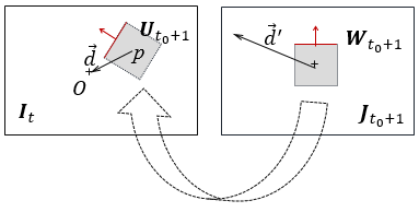
Fig.2. The first step of the algorithm. The region ![]() in
the frame
in
the frame ![]() matches
of the central part
matches
of the central part ![]() of
the current frame
of
the current frame ![]() . The
vector
. The
vector ![]() in
in ![]() corresponds
to the vector
corresponds
to the vector ![]() . The
red arrows denote the drone course with respect to frames
. The
red arrows denote the drone course with respect to frames
again for the current frame ![]() and
the supplied frame
and
the supplied frame ![]() or
one of its nearest predecessors. Thus, until discrete time
or
one of its nearest predecessors. Thus, until discrete time ![]() frames
frames
![]() and
supplied
and
supplied ![]() (either
one of its nearest predecessor) are used for the navigation. In general, the
replacement of supplied image
(either
one of its nearest predecessor) are used for the navigation. In general, the
replacement of supplied image ![]() takes
place at time
takes
place at time ![]() . The
process is repeated until it reaches the first supplied frame
. The
process is repeated until it reaches the first supplied frame ![]() .
.
Notice, that in a case of navigation of a real UAV the described general scheme can be (and is likely to be) modified. The use of interframe information and stabilizing filters (like Kalman or others) may improve the accuracy and reliability of the drone autonomous navigation, but we restrict ourselves to describing the basic principles of our approach and show the applicability of our algorithm by computer simulations.
A step by step description of the algorithm is given below.
Step 1. At the start time ![]() of
the algorithm, to create the image
of
the algorithm, to create the image ![]() ,
consisting of the central part of the current frame
,
consisting of the central part of the current frame ![]() . To
assign the value
. To
assign the value ![]() .
.
Step 2. To find in the previously supplied frames ![]() the
region
the
region ![]() of
the best correspondence to the image
of
the best correspondence to the image ![]() (Fig.
2) with help of correlation or some another algorithm [7‑8].
(Fig.
2) with help of correlation or some another algorithm [7‑8].
Step 3. To test the hypothesis of reality of the
found best correspondence ![]() and
and ![]() . If
it is false, then STOP, else to store the number
. If
it is false, then STOP, else to store the number ![]() of the frame
of the frame ![]() containing
the best correspondence.
containing
the best correspondence.
Step 4. To find the vector ![]() that
starts at the center of
that
starts at the center of ![]() with
respect to
with
respect to ![]() and
ends at the center of
and
ends at the center of ![]() .
.
Step 5. To determine the vector ![]() of
the real displacement of the UAV to the landscape point corresponding the
center of the frame
of
the real displacement of the UAV to the landscape point corresponding the
center of the frame ![]() . The
length of the vector is
. The
length of the vector is ![]() ,
where
,
where ![]() is
the drone altitude at current time
is
the drone altitude at current time ![]() , and
, and ![]() is
the focal distance of the camera. The orientation of the vector with regard to
the current course of the drone is determined via the yaw, which is equal to
the angle between the projection of the course vector onto the frame
is
the focal distance of the camera. The orientation of the vector with regard to
the current course of the drone is determined via the yaw, which is equal to
the angle between the projection of the course vector onto the frame ![]() (red
arrow in Fig.2 left) and the vector
(red
arrow in Fig.2 left) and the vector ![]() .
.
Step 6. If the length of the vector ![]() is
less than the predetermined
is
less than the predetermined ![]() , then go to Step 9.
, then go to Step 9.
Step 7. To move the drone by the vector ![]() .
.
Step 8. To create the image ![]() of
the central part of
of
the central part of ![]() . Go
to Step 2.
. Go
to Step 2.
Step 9. If ![]() , then
to set
, then
to set ![]() and
go to Step 2, else STOP.
and
go to Step 2, else STOP.
The following section presents the results of testing of our algorithm.
3. Experiments
Several video sequences, shot by the onboard camcorder of the quadcopter Fantom 3 Professional, have been used to test the proposed algorithm. We also simulated the process of the autonomous navigation with help of the hand-held usb-camera. Because of inability to integrate the developed algorithm into the inertial navigation of the Fantom 3 Professional, we had to simulate its flight in accordance with the navigation process.
To simulate the drone flight, the projection ![]() of
the vector
of
the vector ![]() onto
the current frame
onto
the current frame ![]() has
been taken instead of the
has
been taken instead of the ![]() (see
Fig.2, right). The vector
(see
Fig.2, right). The vector ![]() was
determined having the length
was
determined having the length ![]() and
the same yaw angle as
and
the same yaw angle as ![]() .
After, the region of the same image
.
After, the region of the same image ![]() with
the center located at the end of the vector
with
the center located at the end of the vector ![]() was
considered as
was
considered as ![]() . The
search of the region
. The
search of the region ![]() corresponding
to
corresponding
to ![]() was
carried out for the same frame
was
carried out for the same frame ![]() . This
step was repeated until
. This
step was repeated until ![]() will
be the center of
will
be the center of ![]() or
the length of
or
the length of ![]() turned
out small enough.
turned
out small enough.
The next step of simulation consisted in selection of the
new “current” frame ![]() (that
actually may differ from
(that
actually may differ from ![]() ). In
order to do that the search was carried out in the reverse direction. The found
). In
order to do that the search was carried out in the reverse direction. The found
![]() (subimage
of
(subimage
of ![]() ) was
compared with local regions of the frame collection
) was
compared with local regions of the frame collection ![]() that
does not contain
that
does not contain ![]() . The
frame
. The
frame ![]() ,
which has the region
,
which has the region ![]() looking
most similar to
looking
most similar to ![]() and
is located far from frame edges, was fixed as the new
and
is located far from frame edges, was fixed as the new ![]() .
Then the simulation continued from Step 2.
.
Then the simulation continued from Step 2.
Simulations have shown applicability of the proposed algorithm at least to the exploited video sequences.
The steps of simulations for several movies made by the
quadcopter Fantom 3 Professional are shown in Fig.3. The task of simulations
was to move the virtual UAV to the point of the landscape that corresponds to
center regions ![]() of
frames
of
frames ![]() shot
during the drone flight from the starting point.
shot
during the drone flight from the starting point.
One of “current” frames ![]() shot
at moment of homecoming drone flight can be seen in Fig.3, right. The starting
position of the virtual quadcopter, which is
shot
at moment of homecoming drone flight can be seen in Fig.3, right. The starting
position of the virtual quadcopter, which is ![]() (red
square), was selected far from the center of
(red
square), was selected far from the center of ![]() in
order to complicate modeling. The steps of simulation are also shown in the
left and right images by red squares. The yellow square is the central area of
in
order to complicate modeling. The steps of simulation are also shown in the
left and right images by red squares. The yellow square is the central area of ![]() . The
navigation iteration finished successfully by displacement of the virtual
quadcopter to the center of
. The
navigation iteration finished successfully by displacement of the virtual
quadcopter to the center of ![]() .
.
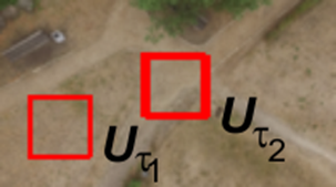
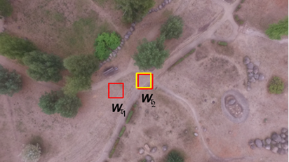
Fig. 3. The right image shows the “current” frame ![]() shot
by the onboard camcorder during the quadcopter homecoming flight. On the left
picture the frame
shot
by the onboard camcorder during the quadcopter homecoming flight. On the left
picture the frame ![]() are
shown that was found as containing the best match
are
shown that was found as containing the best match ![]() for
for ![]() .
Correspondent local regions
.
Correspondent local regions ![]() and
and ![]() are
depicted by red squares
are
depicted by red squares
Figure 4 contains corresponding local regions ![]() and
and ![]() of
frames
of
frames ![]() and
and ![]() , made
during the drone flight from the starting point and back to it. The frames
have different colors, because they are made from different altitudes.
, made
during the drone flight from the starting point and back to it. The frames
have different colors, because they are made from different altitudes.
|
|
|
|
|
|
|
|
|


Fig. 4. Examples of found corresponding local regions ![]() and
and ![]() of
frames
of
frames ![]() and
and ![]()
Simulations demonstrated stability of the matching process
of correspondent regions ![]() and
and ![]() in
frames
in
frames ![]() and
and ![]() . They
also proved adequacy of the found vectors
. They
also proved adequacy of the found vectors ![]() of
virtual drone displacements, which were one of the main elements of the virtual
navigation. The accuracy of the estimation of modeled drone trajectories,
constructed with help of real video sequences captured by the on-board
camcorder of quadcopter DJI Fantom 3 Professional, turned to be equal to1-2
pixels.
of
virtual drone displacements, which were one of the main elements of the virtual
navigation. The accuracy of the estimation of modeled drone trajectories,
constructed with help of real video sequences captured by the on-board
camcorder of quadcopter DJI Fantom 3 Professional, turned to be equal to1-2
pixels.
It should be noted, that the accuracy and reliability of the proposed algorithm depends mainly on the accuracy and reliability of matching frames, captured by the on-board video camera during the drone flight from the starting point and returning home. The authors carried out comparative analysis of correlation algorithms, and also such algorithms as SIFT, SURF, KAZE, AKAZE, LATCH and others, which can be used to match regions of video frames. The analysis has been done for video sequences of city, nature and rural landscapes of European type. Correlation algorithms and the SURF provided reliability of estimation of drone location (which was measured as percentage of correctly found matches) more than 95%, and accuracy of correctly found drone locations at worst was 2-4 meters. Achieved characteristics provide reliable navigation drones in autonomous flight.
4. Conclusion
The algorithm to return home an autonomously flying drone, equipped with one onboard camcorder without a distance meter is proposed. For that, a videosequence shot by the camcorder of the drone during its flight from the starting point along the given route in presence of external navigation signals and frames made by the camera at moments of drone homecoming motion have been used.
The results of simulations of the process of drone navigation for several video sequences containing city and nature landscapes of European type are mentioned. In all computational experiments, the virtual quadcopter returned to the starting point. Accuracy of its trajectory estimates at worst (at high altitude) was 2-4 meters.
Discussion
The authors understand that practical results of the proposed algorithm application will depend on characteristics of technical systems. They will be glad to take part in adaptation of the algorithm to apply it for navigation of small sized drones.
References
1. Bessputnikovaya navigaciya BPLA: Nauchno-tehnicheskiy daidjest ministerstva oborony Rossiyskoy Federacii [Navigation of UAV without use of satellites: Science and Technology Digest of Ministry of Defence of the Russian Federation]. 2012, May 13-26, p. 22.
2. Tishenko I.P., Stepanov D.N., Fralenko V.P. Razrabotka sistemy modelirovaniya avtonomnogo poleta bespilotnogo letatelnogo apparata [Development of system simulating autonomous flight of unmanned aerial vehicle]. Programnye produkty i sistemy. - Programnye produkty i sistemy [Software Products and Systems], 2012, 3(12), p. 3-21.
3. Stepanov D.N. Metody i algoritmy opredelenya polozheniya i orientacii bespilotnogo letalnogo apparata s primeneniem bortovyh videokamer [Methods and algorithms for determining position and orientation of unmanned aerial vehicle with use of onboard videocameras]. Programnye produkty i sistemy [Software Products and Systems], 2014, 1(105), p. 150-157.
4. Engel J., Sturm J., Cremers D. Camera-Based Navigation of a Low-Cost Quadrocopter. RSJ International Conference on Intelligent Robots and Systems (IROS 2012), 7-12 Oct. 2012, Portugal. P. 2815-2821.
5. Blösch M. , Weiss S., Scaramuzza D., Siegwart R. Vision Based MAV Navigation in Unknown and Unstructured Environments. 2010 IEEE International Conference on Robotics and Automation (ICRA 2010), 3-7 May 2010, USA. P. 1-9.
6. Brockers R. et al. Towards autonomous navigation of miniature UAV. Proc. IEEE Conf. on Computer Vision and Pattern Recognition Workshops (CVPR2 014), 23-28 June 2014, USA. P. 645-651.
7. Lowe D. Object recognition from local scale invariant features. Proc. Int. Conf. on Computer Vision ICCV. Corfu, 1999. P. 1150–1157.
8. Bay H. Et al. Surf: Speeded up robust features Proc. 9th Europ. Conf. on Computer Vision ECCV. Graz, 2006. P. 404–417.