SATELLITE IMAGE COMPRESSION TECHNIQUE USING NOISE BIT REMOVAL BY RIDGELET AND INTEGER WAVELET TRANSFORMS
Khaled Sahnoun1, Noureddine Benabadji1
1 Laboratory of Analysis and Application of Radiation (LAAR), Department of Engineering Physics, Faculty of Physics, Universite des Sciences et de la Technologie d'Oran Mohamed Boudiaf, USTO-MB, BP 1505, El M'naouer, 31000 Oran Algerie;
Email: khaled.sahnoun@univ-usto.dz, benanour2000@yahoo.com
Contents
2.1 Continuous ridgelet transform
2.1.1 Ridgelet transform and Radon transform
2.1.2 Discrete ridgelet transform
2.2.1 Scalar quantization of the smoothed band
Abstract
In this article, we present a new satellite image compression scheme that uses Ridgelete and Integer Wavelet Transform (IWT). The main objective of this new algorithm is to achieve a high compression ration as possible with minimal distortion. The basic idea to achieve high compression is to remove or delete the noisy bits from the satellite image using Discrete Analytical Ridgelet Transform (DART), in the first step and decorrelate the pixels to compact the energy into few components with the IWT in the second step. A vector quantization and coding are applied afterwards. The compression performance was evaluated on satellite imagery; the results obtained by the proposed method are satisfactory. The comparison with JPEG compression shows the strengths of this strategy.
Keywords: Satellite Image, Image Denoising, Compression, Ridgelet, DART, IWT.
1. Introduction
The volume of observation images of the earth acquired by satellites is currently rising sharply. This is mainly due the evolution of user needs. Today they wish images available in a very short time after acquisition and updated frequently. Compressing images on board satellites reduces the volume of data transmitted to the ground and therefore to transmit a larger number of images in a brief time. In this frame work we are interested in new transform coding techniques that would allow a gain in compression ratio for an identical satellite image quality. The transforms presented in this paper are based on a version of the wavelet transform adapted to the satellite image compression to maintain high image quality.
When looking, capture or transmit a satellite image of an object, we intuitively see the major problem: the presence of noise. This affects the quality and the size of satellite image. It is therefore interesting to develop methods that can remove noise from the original image before applying a rigorous decorrelation with IWT.
In our case, we studied in this paper a new mathematics transformation: ridgelet transform. This is an improvement of the wavelet transform, and has great potential in image compression, noise reduction and signal processing. Ridgelet transform also has the advantage in highlighting geometric details, image denoising applications, Contour detection…, etc [1].
This paper is organized as following: The first part is the real introduction to this work and presentation of the satellite images compression; the second part concerns the proposed method. In the third part, we study the obtained results, in the fourth and the fifth part a conclusion and bibliography.
2. Method
2.1 Continuous ridgelet transform
In the case of image (2D) the wavelet use the separability
principle with wavelet (1D), we filter horizontally and vertically. The image
analysis is then done following three main directions (horizontal, vertical and
oblique). The image content is not limited to these three directions; it is
easy to understand the need for tools keeping the benefits of multi-resolution
analysis proposed by wavelet and incorporating the concept of directionality
more finely. Hence the creation of a new transformed more generally taking into
account these requirements: ridgelet transform. The ridgelet functions ![]() are
defined the same way as the wavelet but by adding the notion of orientation [2]
(controlled by the parameter
are
defined the same way as the wavelet but by adding the notion of orientation [2]
(controlled by the parameter ![]() )
)
![]()
![]()
So ![]() is
constant following lines
is
constant following lines
![]()
Is a wavelet ![]() In
the transverse direction of these lines let the function
In
the transverse direction of these lines let the function![]() . The
coefficients of the ridgelet transform are given by:
. The
coefficients of the ridgelet transform are given by:
![]()
The reconstruction formula is given by
![]()
2.1.1 Ridgelet transform and Radon transform
We begin by recalling the definition of the Radon transform. The Radon transform was established in 1917 by Johann Radon. It allows to identify the linear forms of a 2D object in an image, integrating image intensity according to all possible lines of the image ranging from a corner θ (figure 1).
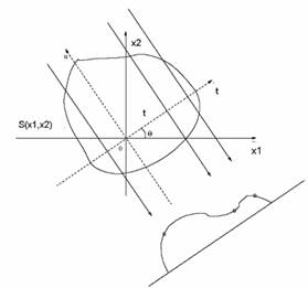
Fig. 1. Principle of the directional integration associated with the Radon transform.
Definition: Radon transform. Either a function![]() . For
. For ![]() . The
Radon transform of
. The
Radon transform of ![]() is
given by:
is
given by:
![]()
Ridgelet transform can be expressed from the Radon
transform, to do this replace the expression ![]() in (2).
Is then obtained
in (2).
Is then obtained
![]()
In other words, the ridgelet transform is obtained by a
wavelet transform 1D of the Radon transform of the image ![]() . One
of the methods for calculate the Radon transform is to use the projection cuts
theorem we calculate the Fourier transform of the image, the image is converted
to a Cartesian grid in an image in polar coordinates, then we apply a inverse
Fourier transform on each lines (for
. One
of the methods for calculate the Radon transform is to use the projection cuts
theorem we calculate the Fourier transform of the image, the image is converted
to a Cartesian grid in an image in polar coordinates, then we apply a inverse
Fourier transform on each lines (for ![]() )
Then we add a wavelet transform 1D following these same lines to obtain the
transformed ridgelet [3,4] see figure 02
)
Then we add a wavelet transform 1D following these same lines to obtain the
transformed ridgelet [3,4] see figure 02
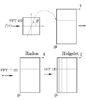
Fig. 2. Construction of the ridgelet transform.
2.1.2 Discrete ridgelet transform
As we have seen, the discrete ridgelet transform is then calculated by four steps:
· the calculation of the Fourier transform of the image;
· the conversion of Cartesian data in polar (Radon transform);
·
applying the inverse Fourier transform for each line having a
direction configured by the angle ![]() ;
;
· the application of the DWT 1D.
The reconstruction of an image by the ridgelet transform follows the reverse steps of the previous [5].
2.1.3 Application
The noise reduction procedure by the ridgelet transform
consists of a simple thresholding of coefficients ridgelet and by calculation
of the inverse transform Thresholding is done from a non-decimated method
developed within the framework of wavelet decomposition. The redundancy of the
wavelet decomposition reduces the artifacts that appear after the thresholding
operation. We use a hard thresholding operation, meaning: update the
coefficients lower a threshold and conservation of others with a threshold ![]() which
can be defined by:
which
can be defined by: ![]() avec
avec ![]()
For the estimation of the noise level![]() , we
consider this level depend the projection index and is estimated using the
median absolute value of the first level of wavelet coefficients for each
radial projection [6]
, we
consider this level depend the projection index and is estimated using the
median absolute value of the first level of wavelet coefficients for each
radial projection [6]
2.2 Subband coding
The transformation by integer wavelet (IWT) can decompose
the image into different sub-bands based on frequency. The wavelet
decomposition is made by lifting scheme that allow perfect reconstruction of
the image during the decompression. The lifting transform consists of
separating the samples even and odd in two different tables. If ![]() is
the input signal, this division is noted [7]:
is
the input signal, this division is noted [7]:
![]()
![]()
The lifting and dual lifting scheme is given by:
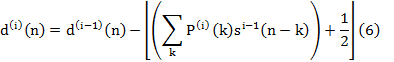
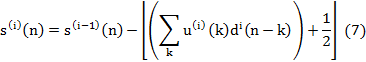
![]() Denotes
the lower integer part.
Denotes
the lower integer part.
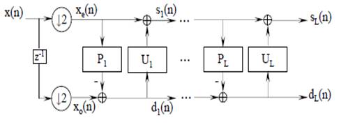
Fig. 3. Lifting scheme [8].
The discrete cosine transform (DCT) was used to encode the
smoothed subband. To do this, each subband has been divided into blocks of ![]() pixels
and discrete cosine transform was calculated for each block, the discrete
cosine transform of block pixel
pixels
and discrete cosine transform was calculated for each block, the discrete
cosine transform of block pixel![]() of
of ![]() pixels
is given by [9]:
pixels
is given by [9]:
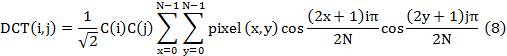
![]()
The inverse transform to restore the block in can be written by:
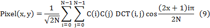
![]()
2.2.1 Scalar quantization of the smoothed band
Scalar quantization is the approximation of each value of
the random signal ![]() by a
value which belongs to a finite set of codes
by a
value which belongs to a finite set of codes
![]() . At
very amplitude
. At
very amplitude ![]() belong to the interval
belong to the interval ![]() we
assign a quantified value
we
assign a quantified value ![]() located
in this interval [10].
located
in this interval [10].
2.2.2 Detail subband coding
2.2.2.1 Algebraic vector quantization
The detail subband are quantified vectorially then transmitted to the receiver. The source vectors have probability densities which can be approximated by Laplace laws.
![]()
![]() is
the standard deviation and
is
the standard deviation and ![]() the
size of the vectors.
the
size of the vectors.
The algebraic vector quantization (AVQ) is a vector quantization, in which the dictionary is a part of a regular network that means: a finite set of regularly arranged points in space. The interest of these quantifiers is the speed quantification by fast algorithms. This is the difference with the techniques based on the LBG algorithm for which the reproduction vectors are arranged in space as a function of the training sequence. This lack of order requires the use of methods of "full-search" more or less prepared to search for the reproduction vector [11].
2.3 Program Structure
The method we have developed is summarized in figure 4. We try to discard noisy bits from the original satellite image by the ridgelet transform after the processed image is decomposed into subband. To do this, we use the integer wavelet transform (IWT) this gives a smoothed subband reflecting the average characteristics of the satellite image and sub-bands representing the details of this picture. Then, the image compression is realized by subjecting a discrete cosine transformation (DCT) to the smoothed sub band and coding the detail subband by algebraic vector quantization. Decompressing satellite image are then obtained by doing the inverse transformation.
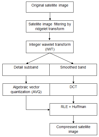
Fig. 4. Program structure.
3. Results
The method realized in C++ to compress a satellite image (256 × 256) excerpt from the Satellite SPOT. The results were obtained by the proposed approach and their discussions are presented. Also, a comparative study with JPEG algorithm is described. These results are expressed on two levels, PSNR and Compression ratio CR. PSNR and CR are expressed by [12]:
![]()
![]()
![]()
![]() :
Length and width of the satellite image.
:
Length and width of the satellite image.
![]() :
The gray level of the image
:
The gray level of the image
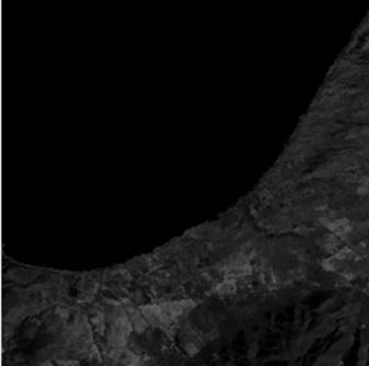
Fig. 5. Original satellite image (1).
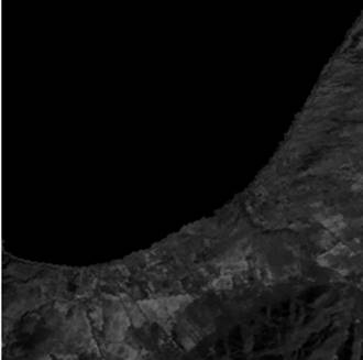
Fig. 6. Satellite image reconstructed (1).
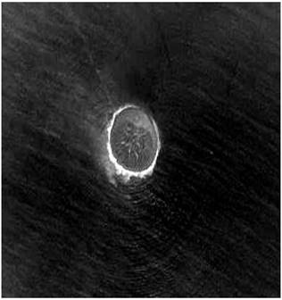
Fig. 7. Original satellite image (2).

Fig. 8. Satellite image reconstructed (2).
Table 1. Table of results with the proposed approach
|
Image (proposed approach) |
PSNR (dB) |
CR (%) |
|
Satellite image (1) |
41,87 |
89,41 |
|
Satellite image (2) |
44,63 |
86,58 |
Table 2. Table of results with JPEG
|
Image (JPEG) |
PSNR (dB) |
CR (%) |
|
Satellite image (1) |
40,09 |
75 |
|
Satellite image (2) |
41,95 |
80 |
Table 1 shows the results obtained for the satellite images. We note that the results of PSNR and CR depend on the nature of the satellite image. We can notice from table 2 that the PSNR and the compression ratio for the proposed approach is best than JPEG.
4. Conclusion
In general, it can be said that the proposed approach can achieve very good results in terms of PSNR and compression ratio CR. it dramatically reduces the amount of data contained in satellite images while maintaining their original properties. These results depend on ridgelet transform, the type of wavelet, the algebraic vector quantization (AVQ) algorithm and the entropy coding used. The results of the AVQ depending on the choice of codebook length and the vectors sizes. The choice of wavelet focuses on the conservation of information, regularity and the number of filter coefficients the first parameter is essential in all compression methods, the two other are associated with the use of the AVQ and minimize distortions, the most regular wavelets that have a reduced number of coefficients give the best results.
5. Bibliography
[1] Candes E. Ridgelets: Theory and Applications. PhD Thesis, Department of Statistics, Stanford University of Stanford, 1998.
[2] Candes E., Donoho D.L. Ridgelets: a key to higher-dimensional intermittency? Phil. Trans. R. Soc. Lond. A., pp. 2495–2509, 1999
[3] Deans S.R. The Radon transform and some of its applications. John Wiley & Sons, 1983.
[4] Do M.N., Vetterli M. Orthonormal finite ridgelet transform for image compression. Proc. IEEE Int. Conf. Image Processing, Sept. 2000.
[5] Do N.M., Martin V. The finite ridgelet transform for image representation. Article IEEE transactions on image processing, 2002
[6] Umaamaheshvari A., Thanushkodi K. Digital image watermaking based on independent component analysis and ridgelet transform. International Journal of Computer Science and Network Security, 2011
[7] Jeyalakshmi, A., Ramyachitra, D. Wavelet transform based watermarking using a simple spread spectrum technique. International Journal of Imaging and Robotics, vol. 01, no. A08, pp. 3-12, 2008.
[8] Bekkouche H. Synthesis of adapted filter banks, application to image compression. PhD Thesis University of south Paris XI France, 2007
[9] G. Abousleman P. Marcellin M W, Hunt B R. Compression of hyperspectral imagery using the 3-D DCT and hybrid DPCM/DCT. IEEE Transactions on Geoscience & Remote Sensing, 1995.
[10] Sahnoun K., Benabadji N. Satellite Image Compression Technique Using Noise Bit Removal and Discrete Wavelet Transform. International Journal of Imaging and Robotics, vol. 15, no.03, 2015.
[11] Gray R.M., Linder T. Mismatch in high rate entropy constrained vector quantization. IEEE Transactions on Information Theory, vol. 49, 5, pp. 1204-1217, May 2003
[12] Navaneethakrishnan, Shanmugaprabha, S., Malmurugan, Novel image compression using discrete balanced multiwavelet transform and the minimum list speck (mls) embedded quantization algorithm. International Journal of Imaging and Robotics, vol. 07, no.01, 11-26, 2012