RESEARCH OF A SPACE DEPTH REPRODUCIBLE BY A MULTI-VIEW AUTO-STEREOSCOPIC SYSTEM
Yu.N. Ovechkis1,3, A.I.Vinokur1,2
1 Moscow State University of Printing Arts;
2 National Research Nuclear University MEPhI (Moscow Engineering Physics Institute);
3 Cinema and Photo Research Institute.
ovechkis@yandex.ru, alex.vinokour@gmail.com
Contents
2. The analysis of a generalized multi-view auto-stereoscopic system
Abstract
In this article, a generalized model of system for formation of a multi-view auto-stereoscopic image, i.e. holographic or raster, is viewed and this system can be used for 3D scientific visualization. It is shown that the space depth is limited in the absence of views’ changes in vertical direction regardless of the number of formed horizontal views and sizes of elementary viewing zones. Analytic expressions for its determination were obtained and it was established that this value lies within the depth of eye sharpness of the observer focused on the plane for image views forming. This restriction can be explained by impossibility of accommodation of an observer’s eyes on the defined image element even if there is an infinitely large number of views in one (horizontal) direction.
Keywords: 3D scientific visualization, multi-view auto-stereoscopic system, view, viewing zone, the depth of sharpness, stereoscopy, holography, stereoholography, raster, lens raster, three-dimensional image.
1. Introduction
Reproduction systems of 3D images that work without using eyeglasses and other special accessories have always attracted attention and aroused great interest of developers and consumers of such equipment because of a totally accurate image and the method of its presentation. Such systems can be used and are already partially used in advertising, television, different devices (i.e. smartphones, tablet computers), at the exhibitions, etc., as well as in various technical applications, training systems, simulators, etc. [1 - 8].
These systems are of undoubted interest in the tasks of scientific visualization: 3D presentation of rapid-flowing processes, complex molecules, elementary particles paths, etc. But there are specific requirements concerned with the tasks of scientific visualization, such as high quality of three-dimensional image with opportunity to examine the object on the one hand and more accessible budget system for researchers on the other hand. Therefore, the problem of optimization of technical characteristics and the system’s parameters of 3D visualization is very urgent. Apart from that, users are often deceived since not a real spatial three-dimensional image with change in views is shown to them but a normal dynamic plane picture as if it was "hanging" in the air, and it is called "holographic". For this purpose, transparent films for projection of plane images [9 - 10], mirrors (including film mirrors) collected in the form of prisms or flat monitors located above or below their tops [11, 12] are used. If the show is well organized, i.e. projectors and monitors are well hidden, the room is dark and proper dynamics of a displayed image are provided, then the audience has the illusion of volumetrical. But that has nothing in common with a true three-dimensional graphic presentation when the observer can see two different views at each moment of time; as the result, the mechanism of binocular vision is in operation, giving an opportunity for assessment of spatial properties of displayed objects.
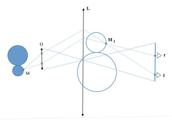
Fig. 1. Schematic diagram of a device that displays a three-dimensional image on the lens. L – lens, O – large aperture lens, M and MI – a certain point of an original object and its image accordingly, V – vision zone, r and l - the right and the left eyes of the observer accordingly.
There are devices that are absolutely different from other similar systems and the image in these systems is being formed in such a way that a certain zone is in the space and two image views within this zone catch the observer's eye and change continuously during their observing, i.e. at vertical and horizontal displacement of the head position. The three-dimensional image projection made by a large aperture lens on a spherical mirror or on a large lens (Fig.1) can serve as an example of such a device.
The image of a pupil of a projection lens O that is formed by the lens L represents a viewing zone V. From this zone a three-dimensional image of the object that is being formed by the objective together with the lens and really placed in the space in front of the specialist can be observed and, what is more important, looked over within not great limits. It is significant that the assessment of spatial properties of the displayed objects is being made by using of both the binocular perception mechanism, i.e. bringing the eye axes on the image element under review (the image M1 of an element M of the original object in Fig. 1), and the accommodative mechanism, i.e. eye focusing on the given element.
The true 3D graphic presentation with naturally horizontal and vertical changeover views is being created also by the image holography [13, 14] or in the system of holographic cinema, proposed by Professor Komar [14 – 16]. The image formation in such a system is also based on use of large aperture lenses at shooting the scene objects on a film-hologram and at the projection (Fig. 1). The creation of viewing zones takes place because of three-dimensional image projection on the holographic screen which is a holographic multifocal spherical mirror, that - similar to a lens (Fig. 1) - transfers the image of the pupil of the projection lens to the observer’s eye and reproduces this image on the seat locations in the cinema hall.
Multi-view auto-stereoscopic take the intermediate position between the above examined plane and three-dimensional images, i.e. glasses-free images with horizontal change of the views. For their creation the lenticular [17 – 22] or holographic techniques [24, 27] are used. In the first case, a special coding, the creation of parallax-panoramagram and the usage of lenticular or slot raster for decoding and views separation are being realized.
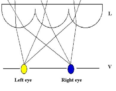
Fig. 2. Schematic diagram of formation and monitoring of an auto-stereoscopic lenticular image
In Fig. 2 a schematic diagram of formation and monitoring of an auto-stereoscopic multi-view image is shown by using a cylindrical lenticular raster L for views separation. In the plane I the so-called parallax-panoramagram is being formed, which is a set of narrow vertical strips, each of them corresponds to one element of decomposition of one view of the displaying object (Fig. 3).
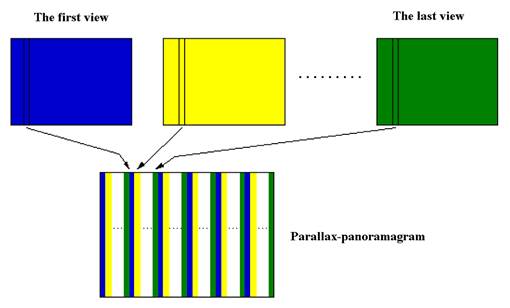
Fig. 3. The formation of a parallax-panoramagram of the multi-view image set
Being located in the field of formation of separate (elementary) viewing zones of each view (plane V) which is the image of the plane I in the lenticular raster L (horizontal), it is possible to see a stereoscopic image because the left and the right eyes catch different views of the object under review (Fig. 2). Moving lengthways the plane V and catching the other pairs of zones, there is presented an opportunity to examine the three-dimensional image within the common viewing zone.
The image of a parallax-panoramagram can be synthesized by computational methods and formed on a different data media. These can be a synthesized photo [17, 18], a projection screen [19, 20] or a television monitor [21 - 23]. In all these cases, the decoding of a parallax-panoramogram is examined by means of the lenticular raster installed in front of the data medium. It is important to note that for more uniform dearness distribution on the display field in the television auto-stereoscopic devices proposed in [22, 23] the inclined position of raster and more complicated color code with programming of color sub-pixels of your monitor display are used.
The recording of synthesized holograms with horizontal view changes is being realized using a set of plane images of separate views of an object [24 – 27]. In the first stage, a holographic sequential shooting of every view is being made on the sequential vertical narrow strips of the future hologram. After that a copy of this hologram is made by a conjugate beam of light and a hologram-copy is installed in the position of the plane view images. At the retrieval of the obtained hologram H by a conjugate beam of light R (Fig. 4), in the space in the position of the first hologram - with regard to the copy - there is arising a set N of separate vertical viewing zones V1, V2, ..., VN of registered views of three-dimensional image of an object images of which are located in the plane of hologram H.
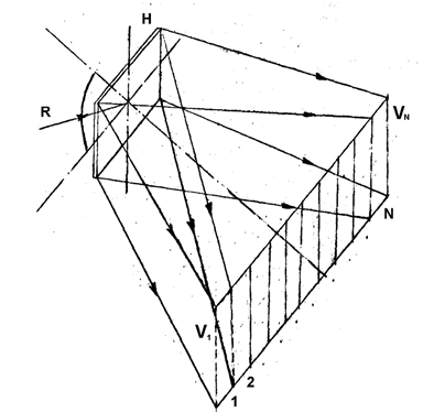
Fig.4. Schematic diagram of the retrieval of a synthesized hologram
Without going into technological details of formation of such lenticular and stereo holographic images, we stress here that they have much in common with formation of a plane in which the images of all views of the displayed object and zone planes for separate viewing of these views are concentrated in coded form. Therefore, different pairs of views catch the observer’s eye depending on his position and he has an opportunity to see the 3D stereoscopic image.
Due to the relative simplicity of the realization and sufficiently high quality of an obtained three-dimensional image there are devices exactly of this kind currently actively developed and partially implemented. Since the number of views in such devices is limited and its overgrowth is usually connected with technological difficulties (e.g., with sinking of diffraction efficiency for holograms with limited resolution of medium in raster systems), it seems to be interesting and necessary to determine the sufficient number of views formed by the system and connect it with the depth of a reproduced space. This research is devoted to this work.
2. The analysis of a generalized multi-view auto-stereoscopic system
Let us consider an auto-stereoscopic system (Fig. 5) with horizontal change of views that forms a vertical plane of their images I in the space as well as the vertical plane of the viewing zone V that consists of elementary viewing zones of each view Vi which are vertical strips of width d. The width of the whole viewing zone
D = N*d, (1)
where N is the number of views of the system. This zone can be single and that is usually the case with stereo-holograms; or zones can be repeated in the plane V and that is the case with lenticular systems.
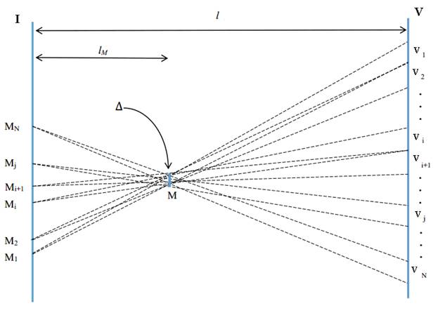
Fig. 5. A generalized model of formation system of an auto-stereoscopic multi-view image
I - plane of views formation of a displayed auto-stereoscopic image,
V - plane of viewing zones formation of this image,
M1, M2, ..., MN - images of N views of the point M of the stereoscopic image reviewing from the single-view viewing zones V1, V2, ... VN,
l - distance between the planes I and V,
lM - distance from the plane I to the point M of an auto-stereoscopic image under review,
Δ - transverse dimension of displacement of the point M stereoscopic image at the eyes moving within the single-view viewing zones.
We also assume that the system is ideal, i.e. edges of the viewing zones are quite sharp and do not intersect. The stereoscopic image of a certain point M that lies in the fore-display space is formed by M1, M2 ... Mi, Mi+1 .... MJ ... MN points of the plane I.
At first, let us consider a case when d > be, where be is the diameter of the eye pupil, and both eyes are lying within a pair of elementary zones corresponding with the eye basis, e.g. Mi and MJ. If the observer stays motionless or if he moves within one pair, only then he will see the usual stereopair image of the point M. In contrast to stereopair, e.g. eye-glasses stereoscopy, if the observer's eye moves to the adjacent pairs of zones Mi+1 and MJ+1 then new views appear, hence giving an opportunity to look over the presenting subject.
This jump is the greater, the further the image of the point M is from the plane I of multi-view images formation; and the larger the size of elementary zones d (Fig. 5) is. It is easy to show that the angular value b of the image displacement relative to the observer when looking over within one pair of zones and that it is equal to:
b = D/*(l + lМ) = d*lМ / l *(l + lМ), (2)
where l and lМ are the distances from the image plane of the image views I to the plane of the viewing zones V and the stereoscopic image M accordingly; the sign “+” refers to the image that lies behind the plane I, the sign “-” in front of it relative to the observer.
If the pupil is on the border of two zones, e.g. Vi and Vi+1, then the image will appear double, two views Mi and Mi+1 (Fig. 5) will catch the eye simultaneously. The angular size of this twin spot, as it can be seen, is also determined by the expression (2).
Thus, while making a natural requirement of imperceptible jumps and double imaging when looking over a multi-stereopair (multi-view) image, we should also require to fulfill the condition b < be, where be is the angular resolution of the observer's eye. As a result, the restriction on the permissible depth of the represented space (for a given size of the elementary zones of viewing) is obtained:
lМ < b e l2/ (d + be l), (3)
where the sign “-” refers to the image that lies behind the plane I, and the sign “+” - in front of it.
If the size of the elementary zone d in the system is less than the diameter of the pupil, then more than one image of different views will always fall into the eye. In this case, in order to observe a single sufficiently sharp image of the given point its maximum distance from the plane of stereopair focusing must comply with the expression (4), where the size of the elementary viewing zone d is substituted by the diameter of the pupil be:
lМ < b e l2/ (be + be l), (4)
where the sign “-” refers to the image that lies behind the plane I, and the sign “+” - in front of it.
This expression determines the maximum depth of the formed multi-view image with the given resolution (be) when the size of the elementary viewing zone is equal to the diameter of the eye pupil. Taking into account (1), we find that the required number of views is N = D / be and that its further growth, in general, is not required. It should be noted that if while creating the system a certain evident blur of formed image is being allowed, i.e. the image is going beyond the scope of be , then - for the elimination of the appeared image fragmentation - it is advisable to reduce the transverse size of the elementary viewing zones as compared to the diameter of the eye pupil. Besides, one should remember that in real systems there are a number of technological factors leading to the deterioration of image quality, i.e. aberration of raster lenses, holograms’ chromatism, light sources extension for their recovery, etc., and as a consequence the mentioned double imaging will be absent.
The analysis of the expression (4) shows that it determines nothing else but the depth of the eye sharpness lying in the plane of viewing zones and focused on the plane of stereo pair formation [28]. Thus, the maximum depth of the volume scene formed by a multi-stereopair method on condition that there is the possibility of its continuous examining is determined by the depth of the eye sharpness of the observer. The reduction of the size of the elementary viewing zones and the growth of the number of views accordingly does not lead to the possibility to increase the depth of the scene at the given sharpness criteria be.
It is important to note that this restriction is connected with the depth of the eye sharpness fully coincides with the limiting characteristic of stereoscopic images and that it is caused by the presence of discontinuity between accommodation and convergence [17, 29].
The physical meaning of this restriction is explained by the fact that in contrast to observation of real objects or their holographic or optical images in which the parallaxes change continuously horizontally and vertically; and the eye has the ability to accommodate (focus) on the point under review (Fig. 1), in the case of stereoscopic presentation where the vertical parallax is absent, the eye is always focused on a single plane, the plane of stereo pairs formation (plane I in Fig. 5). Moreover, even if the size of viewing zone of a single view is smaller than the diameter of the pupil, the observer sees several views of the point under review at the same time, but he is unable to focus on it due to the absence of vertical parallax.
In fact, we consider the extreme case when the system is formed so that the size d of the elementary viewing zones tends to zero. Let the observer's eye to be focused in horizontal plane at the point M (Fig. 2). This leads to the fact that the scattering spot will appear in the vertical plane because there are no changes of the views in this direction, and the rays emanating from a single point - located in the plane I - catch the pupil, having a finite non-zero size. Artificial astigmatism at which the planes of the eye focusing in horizontal and vertical directions are not congruent will be created.
In the table 1 (next page) the dependences of possible depth of the reproducible space (lМ) on the distance of observation of an auto-stereoscopic multi-view image (l) at different values of be; and of the elementary zone width of eye viewing: d < de и d > de are shown. We note that the obtained values are well matched with the experimental data obtained in other works, especially with depth values of the reproducible space for auto-stereoscopic display with raster [21] and the projection glasses-free modular multi-view system [30].
|
sharpness (βmax, angle min.) |
1 |
1 |
1 |
1 |
1 |
1 |
|
Distance (l, mm) |
300,00 |
600 |
1000,00 |
4000,00 |
6000,00 |
8000,00 |
|
zone (d, mm) |
4,00 |
4,00 |
4,00 |
4,00 |
4,00 |
4,00 |
|
Depth+ (lM+, mm) |
6,60 |
25,84 |
69,77 |
923,08 |
1862,07 |
3000,00 |
|
Depth- (lM-, mm) |
6,91 |
28,27 |
81,08 |
1714,29 |
4909,09 |
12000,00 |
|
|
|
|
|
|
|
|
|
sharpness (βmax, angle min.) |
2 |
2 |
2 |
2 |
2 |
2 |
|
Distance (l, mm) |
300 |
600 |
1000 |
4000 |
6000 |
8000 |
|
zone (d, mm) |
4 |
4 |
4 |
4 |
4 |
4 |
|
Depth+ (lM+, mm) |
12,92 |
49,54 |
130,43 |
1500,00 |
2842,11 |
4363,64 |
|
Depth- (lM-, mm) |
14,14 |
59,34 |
176,47 |
6000,00 |
54000,00 |
∞ |
|
|
|
|
|
|
|
|
|
sharpness (βmax, angle min.) |
3 |
3 |
3 |
3 |
3 |
3 |
|
Distance (l, mm) |
300,00 |
600 |
1000,00 |
4000,00 |
6000,00 |
8000,00 |
|
zone (d, mm) |
4 |
4 |
4 |
4 |
4 |
4 |
|
Depth+ (lM+, mm) |
18,97 |
71,37 |
183,67 |
1894,74 |
3446,81 |
5142,86 |
|
Depth- (lM-, mm) |
21,72 |
93,64 |
290,32 |
36000,00 |
∞ |
∞ |
|
|
|
|
|
|
|
|
|
sharpness (βmax, angle min.) |
5 |
5 |
5 |
5 |
5 |
5 |
|
Distance (l, mm) |
300 |
600 |
1000 |
4000 |
6000 |
8000 |
|
zone (d, mm) |
4 |
4 |
4 |
4 |
4 |
4 |
|
Depth+ (lM+, mm) |
30,34 |
110,20 |
272,73 |
2400,00 |
4153,85 |
6000,00 |
|
Depth- (lM-, mm) |
38,03 |
174,19 |
600,00 |
∞ |
∞ |
∞ |
|
|
|
|
|
|
|
|
|
Sharpness (βmax, angle min.) |
2 |
2 |
2 |
2 |
2 |
2 |
|
Distance (l, mm) |
300 |
600 |
1000 |
4000 |
6000 |
8000 |
|
zone (d, mm) |
10,00 |
10,00 |
10,00 |
10,00 |
10,00 |
10,00 |
|
Depth+ (lM+, mm) |
5,30 |
20,85 |
56,60 |
774,19 |
1588,24 |
2594,59 |
|
Depth- (lM-, mm) |
5,50 |
22,41 |
63,83 |
1263,16 |
3375,00 |
7384,62 |
|
|
|
|
|
|
|
|
|
sharpness (βmax, angle min.) |
3 |
3 |
3 |
3 |
3 |
3 |
|
Distance (l, mm) |
300,00 |
600 |
1000,00 |
4000,00 |
6000,00 |
8000,00 |
|
zone (d, mm) |
10,00 |
10,00 |
10,00 |
10,00 |
10,00 |
10,00 |
|
Depth+ (lM+, mm) |
7,89 |
30,74 |
82,57 |
1058,82 |
2103,90 |
3348,84 |
|
Depth- (lM-, mm) |
8,32 |
34,25 |
98,90 |
2250,00 |
7043,48 |
20571,43 |
|
|
|
|
|
|
|
|
|
sharpness (βmax, angle min.) |
5 |
5 |
5 |
5 |
5 |
5 |
|
Distance (l, mm) |
300,00 |
600 |
1000,00 |
4000,00 |
6000,00 |
8000,00 |
|
zone (d, mm) |
10,00 |
10,00 |
10,00 |
10,00 |
10,00 |
10,00 |
|
Depth+ (lM+, mm) |
12,92 |
49,54 |
130,43 |
1500,00 |
2842,11 |
4363,64 |
|
Depth- (lM-, mm) |
14,14 |
59,34 |
176,47 |
6000,00 |
54000,00 |
∞ |
|
|
|
|
|
|
|
|
|
sharpness (βmax, angle min.) |
2 |
2 |
2 |
2 |
2 |
2 |
|
Distance (l, mm) |
300,00 |
600 |
1000,00 |
4000,00 |
6000,00 |
8000,00 |
|
zone (d, mm) |
30,00 |
30,00 |
30,00 |
30,00 |
30,00 |
30,00 |
|
Depth+ (l+, mm) |
1,79 |
7,11 |
19,61 |
296,30 |
642,86 |
1103,45 |
|
Depth- (l-, mm) |
1,81 |
7,29 |
20,41 |
347,83 |
818,18 |
1523,81 |
|
|
|
|
|
|
|
|
|
sharpness (βmax, angle min.) |
3 |
3 |
3 |
3 |
3 |
3 |
|
Distance (l, mm) |
300,00 |
600 |
1000,00 |
4000,00 |
6000,00 |
8000,00 |
|
zone (d, mm) |
30,00 |
30,00 |
30,00 |
30,00 |
30,00 |
30,00 |
|
Depth+ (lM+, mm) |
2,68 |
10,61 |
29,13 |
428,57 |
915,25 |
1548,39 |
|
Depth- (lM-, mm) |
2,72 |
11,00 |
30,93 |
545,45 |
1317,07 |
2526,32 |
|
|
|
|
|
|
|
|
|
sharpness (βmax, angle min.) |
5 |
5 |
5 |
5 |
5 |
5 |
|
Distance (l, mm) |
300,00 |
600 |
1000,00 |
4000,00 |
6000,00 |
8000,00 |
|
zone (d, mm) |
30,00 |
30,00 |
30,00 |
30,00 |
30,00 |
30,00 |
|
depth+ (lM+, mm) |
4,43 |
17,48 |
47,62 |
666,67 |
1384,62 |
2285,71 |
|
depth- (lM-, mm) |
4,57 |
18,56 |
52,63 |
1000,00 |
2571,43 |
5333,33 |
3. Conclusion
An analysis of a generalized holographic and lenticular system of forming a multi-view auto-stereoscopic image was conducted and on its basis the ratios determining the connection between the depth of a reproduced stereoscopic image and the dimensional parameters of the system, i.e. the viewing distance and the size of elementary viewing zones of single views, were obtained; and it was shown that:
- the depth of reproduced space is limited irrespective of the number of the views formed in the system and of the sizes of the elementary viewing zones;
- the maximum depth of the space that can be reproduced by the system lies within the sharpness depth of the observer's eye which is focused on the plane of forming the view images. Width of the viewing zone of a single view for joint perception should be equal to the diameter of the eye pupil (4 mm). The further width reduction of this zone does not lead to the growth of possible depth of the reproduced space.
References
1. http://www.telemultimedia.ru/art.php?id=489
2. http://habrahabr.ru/company/yotadevices/blog/237331/
3. http://total3d.ru/trends/92954/
4. http://geektimes.ru/post/208342/
5. http://www.3dnews.ru/923601
6. http://www.smartphone.ua/news/takee_p1__planshet_s_84dyuymovym_qhd_3d-displeem_46762.html
7. https://hi-tech.mail.ru/news/russian-anathomic-table-3d-glass-for-surgery/
8. Vinokur A.I. Information Technologies in Culture and Education: Image Processing Issues. Modern Applied Science, vol. 9(5), pp. 314-322, 2015.
9. http://www.iventashow.ru/service/additional/holo
10. http://waterstone.uz/golograficheskaya-video-proekciya
11. http://www.gefestcapital.ru/holopiramids.html
12. http://www.evolutionmusic.ru/3d-piramid.html
13. Vanin V.A. Izobrazitel'naja golografija. Retrospektivnyj obzor i prognoz [Graphic holography. A retrospective review and forecast]. The world of cinema technology. 2006, no. 4, pp. 17 – 22. [In Russian]
14. Komar V.G., Serov O. B. Izobrazitel'naja golografija i golograficheskij kinematograf [Graphic holography and holographic cinematography.]. Iskusstvo. 1987, pp. 286. [In Russian]
15. Komar V.G. O golograficheskom kinematografe [About holographic cinematography]. The world of cinema technology. 2007, no. 6, pp. 4 – 7. [In Russian]
16. Komar V.G., Principle of the Holographic Cinematography. Selected Papers on Fundamental Techniques in Holography SPIE Milestone Series, vol. MS 171, 2001.
17. Valjus H.A. Stereofotografija. Stereokino. Stereotelevidenie. [Stereo Image. Stereoscopic. Stereo television.] Iskusstvo, 1986. [In Russian]
18. Valjus N.A. Stereoskopija [Stereoscopy]. ANSSSR. 1962. pp. 580. [In Russian]
19. Elkhov V.A., Kodratiev N.V., Ovechkis Y.N., Pautova L.V. A Modular Projection Autostereoscopic System for Stereo Cinema. Stereoscopic Displays and Applications XX, San Jose, California, US, SPIE Vol. 7237, pp. 72370D-1 – 72370D-11, 19 – 21 January 2009.
20. Elhov V.A., Kondrat'ev N.V., Ovechkis Ju.N., Pautova L.V. Ustrojstvo dlja demonstracii rastrovogo stereoskopicheskogo izobrazhenija s vysokim razresheniem [Device for demonstration raster stereoscopic images with high resolution]. The Russian patent for invention number 2391689, priority of May 29, 2008. http://www.freepatent.ru/patents/2391689. [In Russian]
21. Elhov V.A., Kondrat'ev N.V., Ovechkis Ju.N., Pautova L.V., Dik M.A. Avtostereoskopicheskij displej na baze bytovogo zhidkokristallicheskogo televizora [Autostereoscopic display based on the domestic LCD TV]. The world of cinema technology. 2014, no. 1, pp. 3 – 9. [In Russian]
22. Berkel van C., Clarke J. Autostereoscopic display apparatus. US Pat, No. 6,064,424, May 2000.
23. Berkel van C., Parker D.W., Franklin A.R. Multi-view LCD Display. Proc SPIE. Stereoscopic Displays and Virtual Reality Systems III. Vol. 2653, P. 32-39, 1996.
24. Bakanas R., Zaharovas S. Cifrovaja izobrazitel'naja golografija dlja muzeev [Digital Art holography for museums]. The world of cinema technology, 2011, no. 22, pp. 20-21. [In Russian]
25. Brothherton-Ratcliffe David. Large format digital Colour Holograms Produced using RGB Pulsed Laser Technology. Proc.7th International Symhosion on Dissplay Holography, ISBN 0955352711, pp. 200-209, 2006, UK.
26. Zacharovas Stanislovas. Advances in Digital Holography. IWHM 2008 International Workshop on Holographic Memories Digests, pp. 55-67, 2008, Japan.
27. Karnaukhov V.N., Merzlyakov N.S., Ovechkis Yu.N. Synthesis of hybrid optical-digital rainbow holograms and stereo holograms. Optics Communications, Vol. 42, no. 1, pp. 10-12, 1982.
28. Artjushin L.F., Barskij I.D., Vinokur A.I. Spravochnik kinooperatora [Handbook of cameraman]. Galaktika-L, 1999, pp. 256. [In Russian]
29. Elhov V.A., Kondrat'ev N.V., Ovechkis Ju.N., Pautova L.V. Osobennosti formirovanija ob#emnogo izobrazhenija v cifrovom stereoskopicheskom kinematografe [Features of formation of three-dimensional image stereoscopic digital cinematography]. The world of cinema technology, 2011, no. 20, pp. 4-8. [In Russian]
30. Komar V.G. O rezkosti izobrazhenija v kinematografe [On the sharpness of the image in cinematography]. Film and Television Technology. 1962, no. 10, pp. 1-11. [In Russian]
31. Elhov V.A., Kondrat'ev N.V., Ovechkis Ju.N., Pautova L.V. Cifrovoj sintez mnogorakursnyh stereoskopicheskih izobrazhenij dlja bezochkovoj rastrovoj demonstracii [Digital synthesis of multi-angle stereoscopic images for glasses-free scanning demonstration]. The world of cinema technology, 2012, no. 24, pp. 21-25. [In Russian]