COMPUTATION AND VISUALIZATION OF FLOWS PAST BODIES IN MUTUAL MOTION
A.L. Afendikov, Ya.V. Khankhasaeva, A.E. Lusky, I.S. Menshov, K.D. Merkulov*
Keldysh Institute of Applied Mathematics (Russian Academy of Sciences), Moscow, Russian Federation
* Lomonosov Moscow State University, Moscow, Russian Federation
andre@keldysh.ru, hanhyana@mail.ru, lutsky@kiam.ru, menshov@kiam.ru, parovoz1991@yandex.ru.
Contents
3. Computation results for motionless bodies
4. Computation results on Cartesian grids with local mesh adaptation
Annotation
The features of the flow past a pair of coaxially placed bodies in mutual motion were considered.
Unsteady flows around separating bodies are quite complex. In this process, one can distinguish several specific stages. When the front part of retracting body is in the subsonic flow behind the front bow shock wave it has little effect on the outside flow. Then body interacts with the bow shock wave and reverse flow region is formed. For some time the two bodies with the region of the reverse flow between them are flown around by external flow as one.
Numerical simulation of moving bodies was made using free boundary method (variation on immersed boundary method) and multilevel Cartesian grids with local adaptation based on wavelet analysis. The dynamics of the interaction of a moving body with the bow shock and the formation of the reverse flow region were studied. Flow dynamics are illustrated by a series of images and animations which show the distribution of density and pressure, stream lines and mesh structure and were obtained using Tecplot. It is these visualization instruments that allow us to see the formation of spatio-temporal structures at various flow regimes and get the qualitative picture of the complex unsteady physical process of the flow around separating bodies.
Keywords: computational fluid dynamics, free boundary method, Cartesian grids, mesh refinement, flow past moving bodies.
1. Introduction
The studies of the flow around a group of bodies moving in relation to each other, are of great theoretical and practical interest. One such practical application is the process of separation of multiblock launch vehicles (LV) of different classes. During the flow past multiblock LV by subsonic, transonic and supersonic flows, and in the process of separation of stages a complicated flow pattern emerges due to the presence of detached flow areas which due to their unsteady nature lead to high levels of fluctuating loads. At great supersonic speeds complex configuration of intersecting shock waves leads to a sharp increase in heat fluxes and power loads in the areas of interaction.
During the separation of the successively arranged bodies of rotation, depending on the distance between bodies two regimes of flow can be observed [1-4]. The first regime can be observed in the initial stage of separation, when the distance between bodies is less than critical. The external flow is formed in the space between the bodies with closed current as a solid continuation of the front body. With the distance increasing to critical closed separated flow between bodies collapses. Restructure of the flow occurs. After the front body a bottom current and in front of the rear body a head shockwave is formed. A second flow regime is formed. Similar regimes emerge in the flow past a group of the motionless bodies.
The analysis of various factors established in [1,3] that the critical distance between the bodies, at which the restructuring of the flow occurs, is dependent on the relative size and shape of the bodies, the Mach number and the Reynolds number. In addition, the critical distance depends on whether it is convergence or separation process. In [3] on the basis of a large number of experimental data a dependence was found, according to which with the increase of Reynolds number critical distance also increases.
All of the above mentioned points are valid for stationary bodies and bodies moving with a small velocity relative to each other. In the case of faster movement, the flow pattern can be more complicated.
Flow features described above are the subject of many works, both of numerical and experimental nature. In [5] a numerical simulation of separation of the two coaxially arranged bodies was carried out, but movement of the body was quite slow there so the flow was quasi-stationary. We are interested in flows with greater speed of separation.
In this paper we consider the results of numerical simulation of flow around a blunt cone with a retractable from it at a rate of M = 0.1 cylinder. For this type of flow free boundary method is well suited [6,7], which makes it quite easy to simulate the motion of bodies. A Cartesian grid is used, which covers both the region of the flow and the area occupied by the solid bodies. To fulfill the boundary condition on the body surface compensatory fluxes of mass, momentum and energy are introduced. One of the major advantages of this approach is the simplicity of grid construction which does not depend on the complexity of the body geometry.
Due to the dynamic nature of the problem it makes sense to adapt the grid to the moving features. For this purpose, we use multilevel Cartesian grids with local adaptation based on wavelet analysis [8-10]. For local evaluation of the smoothness of the grid function a criteria based on wavelet decomposition on local templates is applied, which allows us to clearly see the location of the discontinuities and large gradients, which in turn helps in the understanding of flow physics.
In order to understand the dynamics of this problem, the results are illustrated by a series of images and animations which show the distribution of density and pressure, stream lines and mesh structure, all of which were obtained using Tecplot [12]. It is these visualization instruments that allow us to see the flow structure of the problem and to get the whole picture of the unsteady process of separation.
2. Problem Statement
The rear body (body 2) is a cylinder with a head part in the form of a truncated cone. Cylinder diameter is 30 mm, cone half-angle is 20°, diameter of the smaller cone base is 10 mm. The speed of the oncoming flow is M = 3.
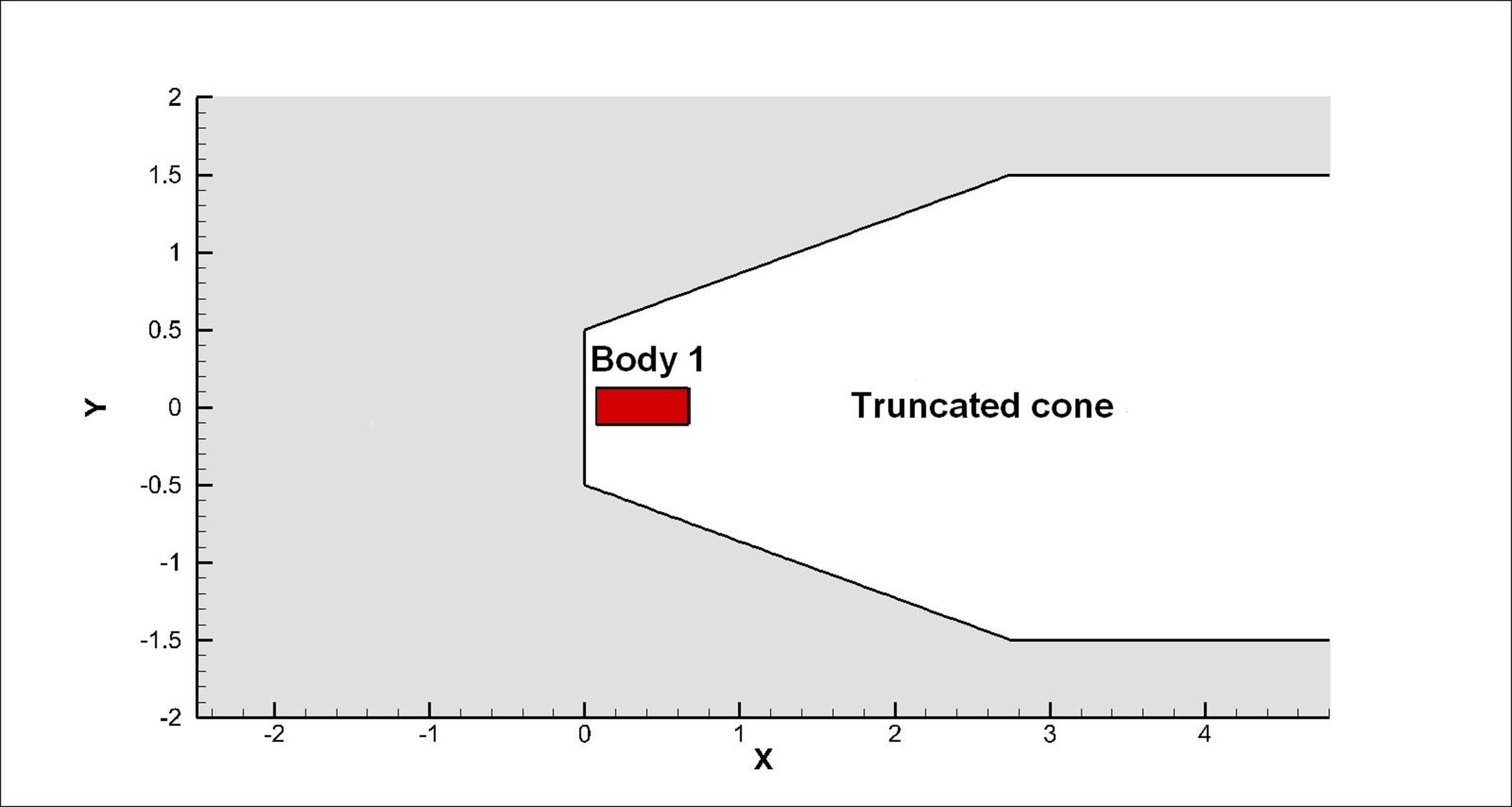
Fig. 1. Scheme of the problem.
Body 1 is a cylinder with diameter 12 mm and length 60 mm and is retracting from body 2 with speed 0.1M. All bodies are represented using the free boundary method. A model of the Euler equations describing the motion of an ideal compressible fluid is used which is solved by the finite volume method with Godunov fluxes. Also a model of Reynolds averaged Navier-Stokes equations with Spalart-Allmaras turbulence model is used. The problem was solved in axisymmetric formulation. Numerical algorithm used had undergone extensive testing, see [11].
All results are illustrated using Tecplot instruments, such as generating streamtraces and arranging consecutive instantaneous fields in an animation. A streamtrace is the path traced by a massless particle placed at an arbitrary location in a steady-state vector field. Streamtraces may be used to illustrate the nature of the vector field flow in a particular region of the plot. The streamtraces are sown together with the pressure distribution.
Calculation of streamtraces in Tecplot uses a two-step second-order Runge-Kutta method which may be summarized as follows:
1. The velocity vector direction is calculated at the current particle position.
2. A small step is made and the velocity vector direction is calculated at the new location. If necessary, the step size is reduced so that no more than one cell is skipped over by the step. The step size is also reduced if a zone boundary is encountered.
3. The vectors obtained in 1 & 2 are averaged and the resulting vector is re-applied at the initial position. The weights of this averaging enforce formal second-order accuracy. To calculate velocities at each point bi- or tri-linear interpolation is used.
3. Computation results for motionless bodies
In the frame of Reynolds averaged Navier-Stokes equations a numerical simulation of flow around motionless bodies 1 and 2, located at some distance from each other, was conducted. Fig. 2 and 3 show instantaneous flow patterns at Re=1015 and Re=1010.
For Re=1015 an unsteady flow regime with occurrence, movement and destruction of multiple vortices in the area between bodies was obtained. At some points in time the flow pattern is close to the first regime described in introduction (Fig. 2, animation 1). For Re=1010 a steady flow with two separation zones after the front body and in front of the rear body is obtained that corresponds to the second flow regime.
These results are consistent with the stated in introduction and [3] points, according to which with an increase of Reynolds number the critical distance increases.
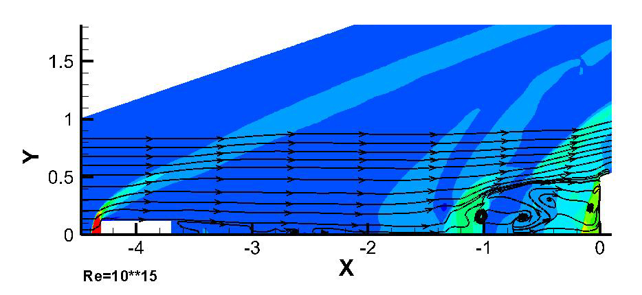
Fig. 2. Density distribution and stream lines, flow around motionless bodies, Re=1015.
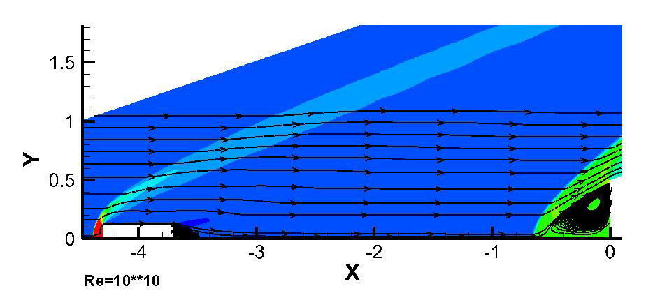
Fig. 3. Density distribution and stream lines, flow around motionless bodies, Re=1010.
In this context, it should not come as a surprise that in the data presented below only the first flow regime is observed because they were obtained in the frame of the Euler equations where Re→∞.
4. Computation results on Cartesian grids with local mesh adaptation
First, we consider only the flow around the body 2 - truncated cone.
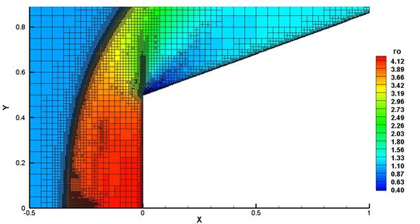
Fig. 4. Density distribution and mesh structure, flow around truncated cone.
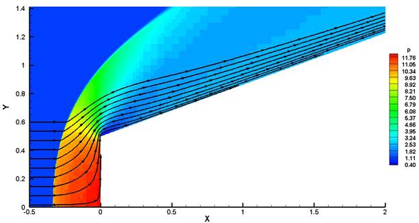
Fig. 5. Pressure distribution, flow around truncated cone.
Mesh adaptation to the solution is conducted based on density field analysis. As Fig. 4 shows, wavelet-analysis captures discontinuities (a strip of small cells at the shock front) and rarefaction waves limited by lines of derivative discontinuities. The unperturbed flow does not require adaptation, therefore, outside the bow shock the cells are of the base level (the biggest size). For the best approximation of the geometry on the boundary of the body cells have the maximum level (the smallest size).
Now let’s consider the case with retracting at a rate of 0.1M body 1. It is assumed that at the initial moment the body 1 is completely inside a truncated cone and instantly starts to move at a speed of 0.1 M upstream. Fig. 6 shows the instantaneous flow patterns at various stages of extension of the body 1.
|
|
|
|
a |
|
|
|
|
|
b |
|
|
|
|
|
c |
|
|
|
|
|
d |
|
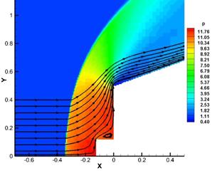
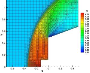
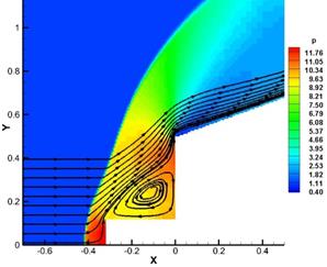
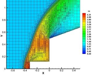
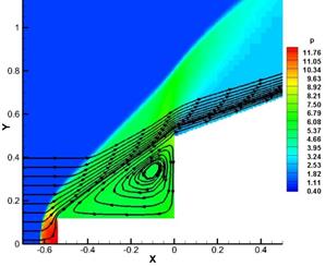
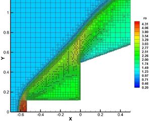
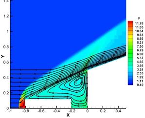
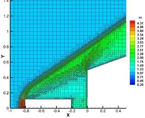
Fig. 6. Pressure distributions and stream lines (on the left) and corresponding meshes with density distributions of the flow around body 2 and extending body 1 at different times.
The general flow pattern is similar to that described in [11], where results were obtained without local mesh adaptation.
Fig. 6a shows body 1 in the subsonic flow behind the front bow shock wave from the truncated cone. Between the lateral part of body 1 and the front portion of body 2, a reverse flow region with subsonic speeds is formed. Currently almost all changes in the grid occur only due to adaptation to the boundary of the body.
Then body 1 intersects the front of the bow shock and warps it (Fig. 6b). Reverse flow region begins to grow in size until it fills the entire space between the body 1 and the side portion of a truncated body. The curvature of the front of the bow shock wave leads to the reconstruction of the grid.
As a result, the body 1, the region of the reverse flow and a truncated cone are flown around by external flow as a single one. Since this region is isolated from the external flow, the density and pressure therein drop with the increase in its size, as shown in Fig. 6c. In this case, you can see how mesh is refined on the boundary of reverse flow, where contact discontinuity begins to form.
Fig. 6d shows body 1 is completely out of the truncated cone. Reverse flow region fills the space between the body 1 and the front edge of a truncated cone. Pressure and density in it continue to drop. Because the rear body has a larger diameter, before its protruding edges the detached shock wave is formed.
Further, outer flow flows around the region of the reverse flow between the two bodies as a continuation of the front body.
An interesting feature can be observed when from the bow shock wave from body 1 separates a side shock wave which moves downstream to the bottom of the body 1. It also limits the front edge of reverse flow between bodies.
5. Conclusion
The features of the flow past a pair of coaxially placed bodies in mutual motion were considered. Visualization tools used in this work allowed us to thoroughly investigate structure of the flow.
Unsteady flow around separating bodies is quite complex. In this process, one can distinguish several specific stages. When the front part of retracting body is in the subsonic flow behind the front bow shock wave it has little effect on the outside flow. Then body interacts with the bow shock wave and reverse flow region is formed. For some time, the two bodies with the region of the reverse flow between them are flown around by external flow as a single one.
The above-mentioned features of the flow around separating bodies require significant further research. The practical significance of this problem is due, in particular, to the aerodynamics of separation of multiblock launch vehicles.
This work was supported by Russian Science Foundation, project 14-11-00872.
References
1. Petrov K.P. Aerodinamika tel prosteishikh form [Aerodynamics of simplest forms bodies]. Izdatelstvo «Faktorial», 1998, 432 s., ISBN 5-88688-014-3. [In Russian]
2. Khlebnikov V.S. The pattern and restructuring of supersonic flow past a pair of bodies. Fluid Dynamics. January 1994. vol. 29, no. 1, pp.123-128.
3. Khlebnikov V.S. Perestroika techeniya mezhdu paroi tel, odno iz kotorykh raspolozheno v slede drugogo, pri sverkhzvukovom obtekanii [Restructuring of the flow between the pair of bodies, one of which is situated in the wake of another at supersonic flow]. Uchenye zapiski TSAGI. 1976. Vol. 7. No. 3. pp. 133-136. [In Russian]
4. Khlebnikov V.S. Osesimmetrichnoe obtekanie pary tel sverkhzvukovym potokom gaza [Axisymmetric flow around a pair of bodies by supersonic flow]. Uchenye zapiski TSAGI, 1978, Vol. 9, No. 6, Pp. 108-114. [In Russian]
5. Vasenev L.G., Vnuchkov D.A., Zvegintsev V.I., Lukashevich S.V., Shiplyuk A.N. Aerodynamic drag measuring for two consistently located axisymmetrical models during their separation. 16th International conference on the methods of aerophysical research, August 19–25, 2012, Kazan, Russia, Proceedings.
6. Menshov I.S., Kornev M.A. Free-boundary method for the numerical solution of gas-dynamic equations in domains with varying geometry. Mathematical Models and Computer Simulations, 2014, vol. 6, No. 6, Pp.612-621.
7. Menshov I. Treating Complex Geometries with Cartesian Grids in Problems for Fluid Dynamics Parallel Computing Technologies. 13th International Conference, PaCT 2015, Petrozavodsk, Russia, August 31-September 4, 2015, Proceedings, LNCS 9251, pp. 528-535, ISBN 978-3-319-21908-0.
8. Merkulov K. Wavelet-Based Local Mesh Adaptation with Application to Gas Dynamics Parallel Computing Technologies. 13th International Conference, PaCT 2015, Petrozavodsk, Russia, August 31- September 4, 2015, Proceedings, LNCS 9251, pp. 426-435, ISBN 978-3-319-21908-0.
9. Afendikov A.L., Davydov A.A., Men'shov I.S., Merkulov K.D., Plenkin A.V. Algorithm for Multilevel Mesh Adaptation with Wavelet-Based Criteria for Gas Dynamic Problems. Keldysh Institute Preprints, 2015, №97, 22 p.
10. Afendikov A.L., Lutsky A.E., Menshov I.S., Merkulov K.D., Plenkin A.V., Khankhasaeva Ya.V. Algorithm of local mesh adaptation based on wavelet analysis with the use of free boundary method. Keldysh Institute Preprints, 2015, No. 94, 20 p.
11. Lutsky A.E., Menshov I.S., Khankhasaeva Ya.V. Vliyanie neodnorodnosti nabegayushchego potoka na sverkhzvukovoe obtekanie zatuplennogo tela [The impact of the incident heterogenic flow on supersonic flow past of a blunt body]. Matem. modelirovanie, 2016, Vol. 28, No. 6-7. [In Russian]
РАСЧЕТ И ВИЗУАЛИЗАЦИЯ ТЕЧЕНИЯ ПРИ ВЗАИМНОМ ДВИЖЕНИИ ТЕЛ
А.Л. Афендиков, Я.В. Ханхасаева, А.Е. Луцкий, И.С. Меньшов, К.Д. Меркулов*
Федеральный исследовательский центр Институт прикладной математики им. М.В. Келдыша РАН, Москва
* Московский государственный университет им. М.В. Ломоносова (МГУ), Москва
andre@keldysh.ru, hanhyana@mail.ru, lutsky@kiam.ru, menshov@kiam.ru, parovoz1991@yandex.ru.
Аннотация
Рассмотрены особенности течения соосного обтекания пары тел, движущихся относительно друг друга.
При разделении последовательно расположенных тел вращения в зависимости от расстояния между телами может наблюдаться два режима обтекания [1-4]. В начальной стадии разделения, когда расстояние между телами меньше критического, внешний поток обтекает образовавшееся пространство между телами с замкнутым течением как “жесткое” продолжение переднего тела. При увеличении расстояния до критического замкнутое отрывное течение между телами разрушается. Происходит перестройка течения, за передним телом образуется донное течение, а перед задним телом образуется головной скачок уплотнения. Образуется второй режим обтекания. Аналогичные режимы возникают при обтекании группы неподвижных тел.
В процессе обтекания разделяющихся тел можно выделить несколько характерных стадий. Когда передний край выдвигаемого тела расположен между головной ударной волной и усеченным конусом в дозвуковой области, оно оказывает незначительное влияние на течение. Далее происходит взаимодействие маленького тела с головной ударной волной и формирование области возвратного течения. В течение некоторого времени оба тела с областью возвратного течения между ними обтекаются сверхзвуковым потоком практически как одно целое.
Расчет обтекания движущихся тел выполнен с использованием метода свободной границы (вариант подхода immersed boundary method). Используется декартовая сетка, покрывающая как область течения, так и область, занятую твердым телом. Для выполнения граничного условия на поверхности тела вводятся компенсационные потоки массы, импульса и энергии. Одно из главных преимуществ подхода – простота построения сетки, которая не зависит от сложности геометрии исследуемого тела. Расчет производился на многоуровневых декартовых сетках с локальной адаптацией. Для локальной оценки гладкости сеточного решения применяется критерий на основе вейвлетных разложений на локальных шаблонах, что позволяет четко определить расположение разрывов и больших градиентов, что в свою очередь помогает в понимании физики течения.
Исследована динамика взаимодействия движущегося тела с головной ударной волной и формирования области возвратного течения. Динамика течения иллюстрируется серией изображений и анимаций, на которых представлены распределения плотности и давления, линии тока и структура сетки и которые были получены с помощью Tecplot [12]. Именно эти инструменты визуализации позволяют нам прослеживать образование пространственно-временных структур при различных режимах течения и получить качественную картину сложного нестационарного физического процесса обтекания разделяющихся тел.
Ключевые слова: вычислительная газовая динамика, метод свободной границы, декартовые сетки, адаптация сеток, обтекание движущихся тел.