DEVELOPMENT OF A GEOMETRIC MODELING SYSTEM FOR ASSEMBLIES OF MODULAR MACHINE TOOLS
A.N. Feofanov1, S.Y. Manelyuk
1 MSTU “Stankin”, Russian Federation.
Contents
2. List requirements for the automated visualization system
3. Overview of development tools used to create geometric modeling systems for modular machine tools
3.1. Open graphics library OpenGL
3.2. Visual development environment Embarcadero C++
3.3. Database management system Microsoft Access
4.1. Organization of data in the database of standardized components
4.2. Development of the automated data management subsystem to visualize modular machine tools
Abstract
This article examines the challenges of development of a geometric modeling system for modular machine tools. Possible universal components of machine tools are listed. An analysis of requirements for the machine tool assembly visualization system is conducted. Based on this analysis development tools are selected and the process of the development is described. An example of database creation of standardized components of modular machine tools for industrial systems is shown. Another example illustrates a fragment of the automated data management subsystem for building visualized layouts of modular machine tools. This visualization system helped to solve problems of constructing layouts of modular machine tools for flexible production lines in the processing of body parts such as the gearbox, developed by the Moscow Special Design Bureau of automatic lines and modular machine tools (ISO SKB AL and AS).
Keywords: Machine tools, machine tool production, visualization of machine tools, modular machine tools, machine tool visualization system, conceptual design of machine tools, geometric modeling of machine tools.
1. Introduction
This material is aimed to address problems that arise during conceptual design stage while creating layouts of modular machines. The objective of this work is to develop an automated visualization system for modular machine tool assemblies at the conceptual design stage. The main function of this system is to show the possibility of assembly of modular machine tools in three-dimensional space from unified components and parts. Due to the complexity of the workpiece configuration problem at the preliminary design stage of modular machine tools, the task to visualize modular machine tools layouts is relevant. In existing software packages, such as the T-Flex, "Compass" and other similar, a designer first has to create a database of visual components for each of nodes, and then to begin to visualize the layout of the machine tool itself. In the proposed approach the machine tool visualization is based on a set of technical parameters of the layout. The software system created on the basis of the proposed approach can be used by designers to develop the layout of modular machine tools at the stage of conceptual design.
2. List requirements for the automated visualization system
During its operation the user should be provided with the following functionality:
· the ability to choose data regarding overall dimensions from a database of all standardized parts and components of modular machine tools by their characteristic description;
· the possibility to constructe different variations of assemblies using all available standardized components;
· the ability to perform basic actions on the model of the assembled machine tool such as scaling, rotation, and other actions that allow the user to assess visually the resulting model;
· the ability to add new components and parts of modular machine tools into the geometric modeling system, extending the existing database;
· the ability to implement a unique system of flags for automatic visualization without additional manipulations (the term "flag" means a scalar attribute – one selected value such as a string, an integer, or a bit value that corresponds to the specifications of a unified node, that allows to set specific characteristics of this node in the system);
· the ability to create a database of dimensions for components and parts and to link it with the systems of flags and visualization.
3. Overview of development tools used to create geometric modeling systems for modular machine tools
3.1. Open graphics library OpenGL
In order to develop a software product that satisfies the requirements listed in the previous section, fairly powerful tools that work with three-dimensional graphics are required. After conducting market research of development tools that work with three-dimensional graphics, the decision was made that it is the most affordable and efficient to use the functionality of an OpenGL graphics library. The functionality provided by a graphics library under the OpenGL standard will aid in the creation of three-dimensional models of objects and a user-friendly interface to perform operations on these models (such as scaling, rotation and translation).
A library utilizing the OpenGL standard incorporates all the necessary functionality within our requirements for work with graphic objects:
· changes to the view and model;
· broad opportunities to work with color;
· automatic removal of hidden lines and surfaces;
· texture mapping.
Programs written using OpenGL can be transferred to almost every platform in order to obtain the same results, whether it is a graphic station or a supercomputer. OpenGL frees the programmer from the task of writing hardware specific software. If the designated device supports a certain function, this function is performed by its hardware, if not, it is executed by the software library. An OpenGL library is the best suited for the C programming language, which we used to write the main part of the automated subsystem. Based on these advantages the decision was made that all three-dimensional modeling of parts and components for modular machine tools will be processed by an OpenGL graphics library.
3.2. Visual development environment Embarcadero C++
In order to select the main development environment for the geometric modeling system for assemblies of modular machine tools the following factors were taken into account:
· the development environment must be fully compatible with the Windows OS;
· the development environment must provide the ability to use commands of an OpenGL graphics library;
· the development environment must allow to access the attached database;
· the development environment should provide efficient data management functionality;
· availability of extensive documentation and easy to learn.
After analyzing all these factors, the decision was made that in order to solve the practical problems of this work the software development environment Embarcadero C++ will be used. It completely meets all specified requirements and therefore its use will greatly simplify the development of the interface and the programming of necessary calculations.
The main advantages of the Embarcadero C++ environment are:
· convenience when creating a large number of forms;
· easy data transfer between created objects;
· full Windows OS compatibility;
· the ability to create forms for debug output.
The operating language of Embarcadero C++ is the C++ programming language which includes error and exception handling thus significantly increasing the stability and reliability of the program. Embarcadero C ++ supports modern methods of accessing data, for example, compatibility with databases of different types. By utilizing the Embarcadero C++ development environment, the possibility of code reuse is improved through inheritance of visual forms and other features of this tool, the most important of which is update caching, filters, background queries, operations on different data formats, etc. All these are arguments in favor of the choice towards the development environment Embarcadero C++.
It is also worth mentioning the high speed of compilation which significantly reduces the cost of debugging separate parts of the program.
3.3. Database management system Microsoft Access
Microsoft Access is generally a database management system. It is used to store data in tabular form and also provides the ability to display it with the help of other embedded resources. Access also allows to develop convenient data entry forms, to process and to update them. Data storage is organized in such a way, that all data is assembled into one file, which greatly simplifies the work with it.
Microsoft Access is the most common database and interacts very well with Windows. It should be mentioned that the use of Microsoft Access is also justified by the possibility of using it directly through Embarcadero C++. This simplifies the process of accessing data in the database.
At the same time Access is a relational database. This means that by using Access, we can address any data of any type and use multiple database tables at the same time. Using of a relational database management system will simplify the data structure and thus simplify the implementation of the project.
Despite the fact that Oracle is the most prevalent database management system in industrial applications, at this stage of the development we use Access because of its simplicity and accessibility, although in the future it is planned to use software aimed at industrial applications.
4. Description of the development process of the geometric modeling system for modular machine tools and the database of standardized components
4.1. Organization of data in the database of standardized components
As was already noted the Microsoft Access database will be used to store data. After the classification of standardized components according to our requirements was examined, we decided to merge different component classes of the same type in a single table. As the result, the opportunity to fully describe the parameters (dimensional specifications) of the standardized nodes became available. This approach has its advantages. The most important is that it is simple to update and add new objects without ascribing them to a specific class.
All standardized components used in the developed subsystem are shown in Fig. 1 [1, 2].
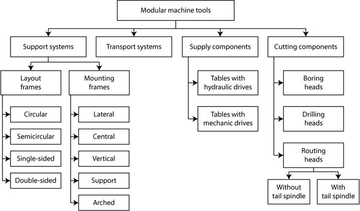
Fig. 1. Diagram of standardized components.
During the database development existing databases were used in order to get the following parameters: side frames; central frames; power supply components; cutting components [3, 4, 5, 6, 7].
The resulting base for this project has also been complemented with missing elements of the support system and the transport system.
The data diagram is shown in Fig. 2.
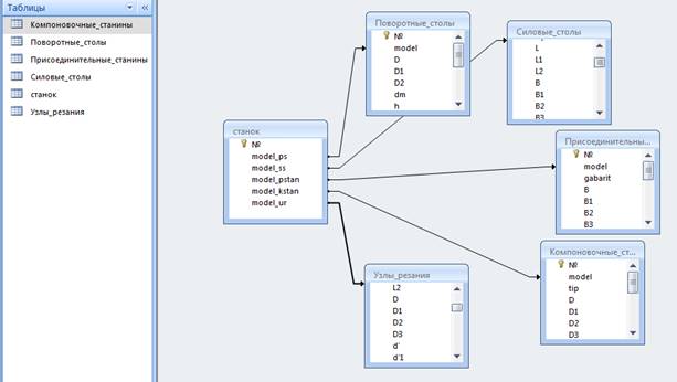
Fig. 2. Data diagram.
Standardized nodes of the type layout frame orient in space all other nodes of the modular machine tools and determine their restrictions, "dead zones" of setup with respect to each other, as well as their orientation on dimensional axes. An example of a table with overall dimensions of layout frames is shown in Fig. 3.
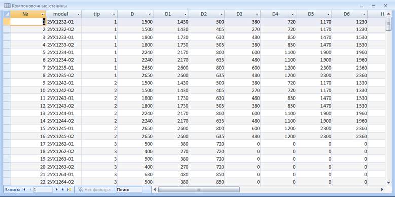
Fig. 3. Layout frames dimensions table.
Thus when the classification was generalized, 5 tables that describe all standardized components relevant to the project were obtained:
· turn tables;
· power tables;
· layout frames;
· mounting frames;
· cutting components [8].
In contrast to our approach we split the category of support systems into two tables: layout frames and mounting frames. This is due to the fundamental difference between them and this separation will simplify the visualization processes of assemblies of the modular machine tools. When one uses layout frames other types of support systems components are not used except for vertical or arched.
This approach to data organization simplifies the expansion process for our subsystem and allows to add radically new components that are not involved in this project at this point [9].
4.2. Development of the automated data management subsystem to visualize modular machine tools
In order to construct various configurations of modular machine tools it is necessary to provide all options of structural pattern creation. To achieve this a specific sequence of forms with certain choices parameter has been designed based on which the user can define any arrangement to meet his requirements, and which also takes into account data understandable to the system in order to create the visualization.
Construction of graphic images of this magnitude without ready-made objects involves a huge number of design options. In order to provide an unambiguous definition an entire system of flags has been developed, which can be populated when the user enters the required information. Then, based on these flags each object is assigned its own number and data that orients it in space.
Let us look at the implementation of the automated visualization system for assemblies of modular machine tools at the conceptual design stage. The program execution begins with user authentication Fig. 4 (database connection check) [10].
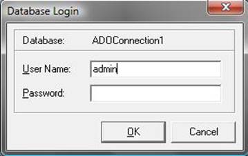
Fig. 4. User authentication screenshot.
Next the initial display of the system is shown, the user receives information about the application, its developers and the usage instructions, what is shown on Fig. 5.
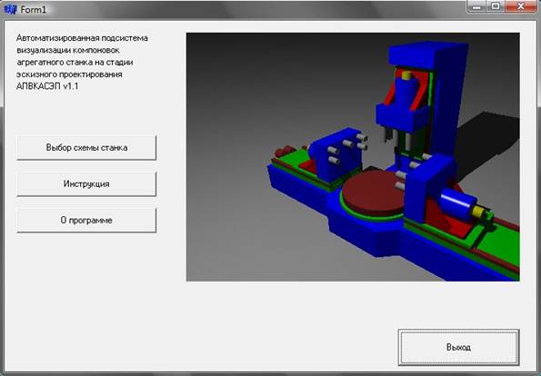
Fig. 5. Initial display screenshot.
During the selection of the option to start the process the user is prompted to choose the type of support frame, as shown in Fig. 6.
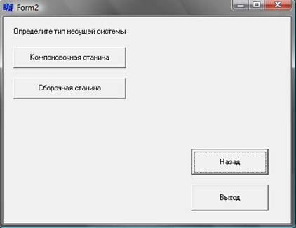
Fig. 6. Support frame selection screenshot.
Depending on the user's choice parameters are entered into the system of flags for object creation and a further definition of the support system is offered, as shown in Fig. 7.
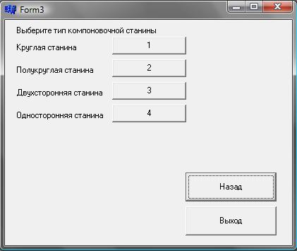
Fig. 7. Layout frame selection screenshot.
Then the main entry form for assembly parameters and layout of the machine tool is shown to the user. For each working group it contains three designs, as shown in Fig. 8:
1. Power table + cutting component.
2. Vertical frame + power table + cutting component.
3. 2 power tables + arched frame + 2 cutting components.
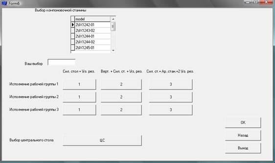
Fig. 8. Working groups definition form screenshot.
Based on the selected options a form with standardized components is selected from the database and shown to the user, as shown in Fig. 9, 10, 11 and 12.
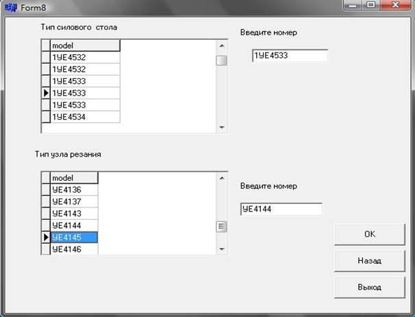
Fig. 9. Definition of the first working group screenshot.
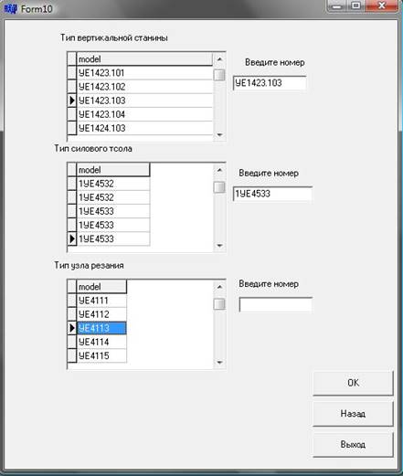
Fig. 10. Definition of the second working group screenshot.
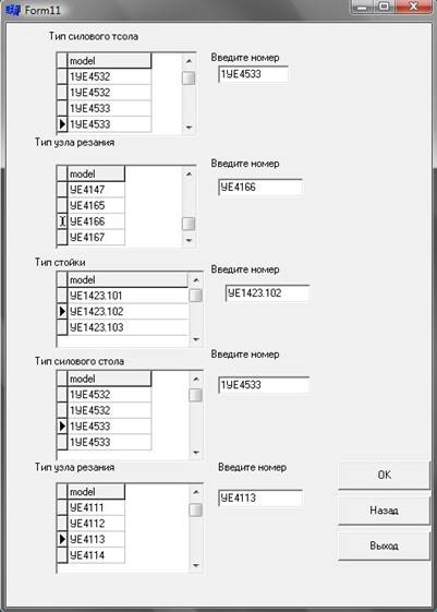
Fig. 11. Definition of the third working group screenshot.
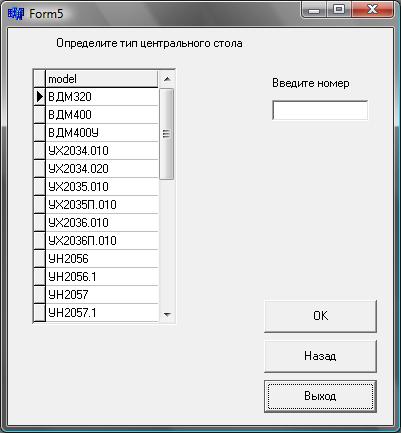
Fig. 12. Turntable selection screenshot.
Once all the required components are selected a form is shown to the user with information about the used standardized components in correlation to their working groups, as shown in Fig. 13.
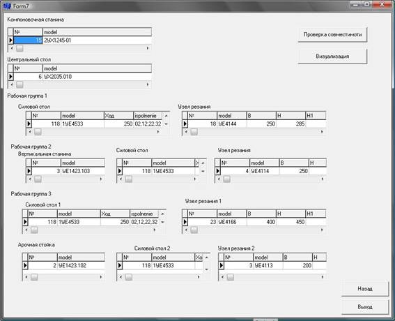
Fig. 13. Composition of the developed machine tool screenshot.
As a result of this process there is an opportunity to verify compatibility. At this stage of development calculations are based solely on overall dimensions and are not affected by the technical features of the machine tool. Existing layouts of modular machine tools also set the restrictions for the use of standardized nodes. The resulting window displays a message about visualization possibility if all the components are selected in accordance with the layout rules.
The visualization is rendered from data stored in the form of a description of the assembly composition and is based on the system of flags. The visualization program consists of a small number of operations to draw standardized components and an interface for using these functions in accordance with the required assembly. A result of the visualization programs execution is shown in Fig. 14.
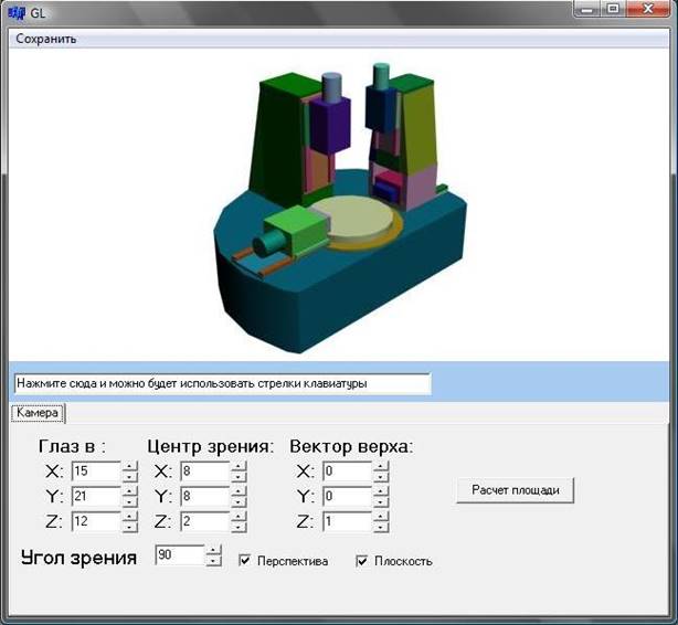
Fig. 14. Visualization of the modular machine tool assembly screenshot.
Fig. 14 shows one of the possible layouts of the selected standardized nodes. A typical layout of the machine with the selected standardized nodes is shown on the screen, provided the given number of sides for body part processing. According to the dimensions of the workpiece the engineer selects the required dimensions and specifications of the standardized nodes of modular machine tools.
Thus, using a database of machine tool components the engineer (on the preliminary design stage) has the ability to visualize the layout of the operational area of technical equipment.
5. Conclusion
Visualization of the layout of the modular machine tool allows an engineer to assess the dimensions of the working zone of the equipment on the conceptual design stage. This approach allows at the conceptual design stage of the development of modular machine tools to reduce significantly (up to 50%) the time of assessment of the operating environment of the equipment, as well as the calculations of the area needed for the equipment and its layout.
This visualization system helped to solve the problems of constructing layouts of modular machine tools for flexible production lines in the processing of body parts such as the gearbox, developed by the Moscow Special Design Bureau of automatic lines and modular machine tools (ISO SKB AL and AS).
References
1. ENIMS: Catalogue Unificirovannye uzly agregatnyh stankov i avtomaticheskih linij [Standardized components of modular machine tools and automated production lines]. Ed. Dr. B.I. Cherepakova. Moscow: VNIITEMR. 1988. 208 p. [In Russian]
2. Feofanov A.N. Gibkie avtomaticheskie linii v mashinostroenii [Flexible automated production lines in mechanical engineering]. Moscow: «Yanus-K». 2002. 192 p. [In Russian]
3. Voronichaev N.M., Genin V.B., Tartakovskiy G.E. Avtomaticheskie linii iz agregatnyh stankov [Automated production lines from modular machine tools]. Moscow: Mechanical engineering. 1971-552 p. [In Russian]
4. Feofanov A.N., Huchlov E.V., Volkova G.S. Issledovanie algoritma processa proektirovanija komponovok agregatnyh stankov i vozmozhnostej ego avtomatizacii [The study of the algorithm of the modular machine tool layouts design process and the possibilities for its automation]. Technology of mechanical engineering. 2005. No. 11. pp. 20-24. [In Russian]
5. Feofanov A.N., Ievlev I.V. Razrabotka struktury dannyh i sostava funkcij sistemy mashinostroitel'nogo proizvodstva [Development of the data structure and production functionality of a mechanical engineering system]. Technology of mechanical engineering. 2006. No. 10. pp. 62-68. [In Russian]
6. Feofanov A.N., Astachova T.A., Kucherenko E.A., Babylov D.A. Razrabotka avtomatizirovannoj sistemy vedenija opisanija uzlov agregatnyh stankov i avtomaticheskih linij [Development of an automated system for modular machine tools and automated production lines nodes description management]. Technology of mechanical engineering. 2007. No. 8. [In Russian]
7. Feofanov A.N., Potapov A.V. Razrabotka bazy dannyh unificirovannyh uzlov agregatnyh stankov [Development of databases for standardized modular machine tool nodes]. MSTU «Stankin» Messenger. 2009. No.3 (7). [In Russian]
8. Kucherenko E.A., Astachova T.A., Babilov D.A., Feofanov A.N. Razrabotka avtomatizirovannoj podsistemy vedenija opisanija uzlov agregatnyh stankov i avtomaticheskih linij [Developing an automated subsystem for storing descriptions of modular machine components and automated production lines]. Technology of mechanical engineering. 2007. No. 8. [In Russian]
9. Volkova G.D. Metodologija avtomatizacii proektno – konstruktorskoj dejatel'nosti v mashinostroenii (uchebnoe posobie) [Methodology of design and construction in mechanical engineering (tutorial)]. Moscow: MSTU «Stankin». 2000. 98 p. [In Russian]
10. Ievlev I.V., Feofanov A.N. Formirovanie trebovanij k sistemam upravlenija bazami dannyh dlja podderzhki opisanija tehnicheskih harakteristik i obrazov unificirovannyh uzlov agregatnyh stankov [Formulating requirements for database management systems for support of technical documentation and images of standardized modular machine tool components]. Technology of mechanical engineering. 2005. No. 11. [In Russian]