MODIFICATION OF WU’S RASTERIZATION ALGORITHM FOR SYSTEMS OF GRAPHIC OBJECT VISUALIZATION
V.M.Lebedev1, D.V. Domashova1, S.V. Gorelov1, N.A. Evstifeeva2
1Financial University under the Government of the Russian Federation, Moscow, Russian Federation
2National Research Nuclear University MEPhI (Moscow Engineering Physics Institute), Moscow, Russian Federation
stud_leb@mail.ru, janedom@mail.ru
Contents
1. Wu’s algorithm for line segment rasterization
1.2. Speed and quality of Wu’s algorithm rasterization
1.2.1. Analysis of algorithm speed
1.2.2. Analysis of algorithm quality
2.1. Overview of the modified Wu’s algorithm
2.2. Comparison of the modified and standard Wu’s algorithms
3. Approbation of Wu’s algorithms
Annotation
The article presents analysis and modification of Wu’s algorithm for automated visualization systems, in respect to overlaying graphic objects of different formats. Comparative analysis of the rasterization speed and quality of the standard and modified Wu’s algorithms as well as recommendations on the use of the algorithms for various map scales are also provided.
Keywords: Wu’s algorithm, rasterization, perspective transformation, distortion factor, vector-based format, raster image
Introduction
Many large architectural and construction companies address the important issue of automated visualization to see how their future constructions might be positioned in space. In many cases, systems of computer-aided design such as AutoCAD and IntelliCAD save results to DWG or DXF vector files. These file formats store images as geometric primitives, such as points, lines, splines and polygons. However, the majority of available photographs or landscape maps are represented in a raster form.
To match a vector-based graphic image to a raster-based one, it is necessary to perform the vector-raster conversion. The process of vector to raster conversion, we call rasterization.
This paper focuses on analysis and modification of Wu’s algorithm [2] with regard to its exploitation in automated visualization systems for overlaying different image formats.
1. Wu’s algorithm for line segment rasterization
1.1. Wu’s algorithm overview
It can be easily seen that there are many ways to convert a vector segment into a raster image. Currently, rasterization is carried out by using the Bresenham and Wu’s algorithms [1-5].
In 1962, Jack E. Bresenham proposed a technique to determine if a pixel of a 2D-raster lies on a line segment by means of integer calculations. His methods comprise Bresenham algorithms for generating 4-connected and 8-connected line segments. Their common disadvantage is drawing line segments with rough and jagged edges.
To mitigate this drawback, Wu Xiaolin introduced an algorithm for smoothing a line segment [2] through painting parts of the segment with different shades, thus diminishing the problem of jaggies. Wu’s algorithm is a method of antialiasing [3-5], hereinafter referred to as the standard Wu’s algorithm.
In order to determine which pixel of a 2D-raster should be associated with a line segment, it is essential to analyze its location relative to the line segment. The main idea of the algorithm is manipulating pairs of pixels with centers straddling the line segment. Here, pixels are squares of side 1 and centers in the nodes of the integer grid. A pixel with coordinates (x, y) means that its center is a point with the said coordinates.
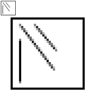
Fig.1. Rasterization of a line segment by Wu’s algorithm
Fig. 2 and 3 show how illuminated pairs are selected from the pixel set. Here, the line is closer to the OX axis than the OY axis, therefore the pairs consist of vertical adjacent elements. If the line were closer to the OY axis, the pairs would be selected from horizontal adjacent elements.
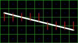
Fig. 2. Pixels selected for painting by Wu’s algorithm
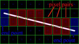
Fig. 3. Pixels painted by Wu’s algorithm
Total brightness of pixel pairs connected with red lines (fig. 2) is 1. The brightness is proportional to the distance from the line segment to the pixel center (fig. 3).
With all its simplicity, Wu’s method is fast and returns high-quality smooth line segments [2].
If coordinates change, a line segment generated by Wu’s algorithm will move smoothly. This enables continuous animation of moving pictures.
1.2. Speed and quality of Wu’s algorithm rasterization
We apply the standard Wu’s algorithm to rasterization of vector-based images and analyze its performance for normal images with regard to two criteria (indicators): speed and quality of rasterization.
1.2.1. Analysis of algorithm speed
Rasterization speed can be estimated in a number of ways, for example, by the execution time and number of iterations required to build a raster-based image. We evaluate the speed in terms of the number of iterations.
It's worth noting that the most complex is drawing a 45-degree line segment. In this case, Wu’s algorithm speed is evaluated for a line segment with coordinates ({0;0};{n;n}).
The algorithm under consideration is linear, i.e. its speed depends on the number of raster points. So, drawing a line segment with coordinates ({0;0};{n;n}) requires n iterations. Results of the analysis shown in Table 1 prove that Wu’s algorithm is rather fast.
In Table 1, the iteration complexity means either the number of iterations for shading a pixel or brightness per pixel.
Table 1. Speed and complexity of rasterization algorithms
|
Algorithm |
Number of iterations |
Complexity of iteration |
|
Wu’s |
N |
2 + o(2) |
1.2.2. Analysis of algorithm quality
Here, algorithm quality means the degree to which a photograph matches the raster image. For measuring algorithm quality, we introduce the term distortion factor that indicates correlation between the obtained image and the expected one.
The distortion factor is calculated as a ratio of the number of unmatched pixels to the total number of pixels measured in per cent (0% - a perfect match, 100% - fully unmatched).
Let us consider an example of calculating the distortion factor.
Case 1. Assume we expected an image shown in Fig. 4 and obtained an image shown in Fig. 5. Here, the distortion factor equals to 30% (3 pixels out of 10 are fully unmatched).
Case 2. We expected an image from Fig. 4 and obtained an image from Fig.6. The distortion factor is 10% (2 pixels out of 10 are partial matches).
|
Fig. 4. An expected raster image |
Fig. 5. A raster image (case 1) |
Fig. 6. A raster image (case 2) |
We introduce errors of the first- and second class. The first-class error shall mean the following: the line should exist, but it is missing. The second-class error shall mean that the line does exist but it should have been missing.
Now we analyze the algorithm in terms of rasterization quality. Note that maximum loss in quality is found in drawing line segments at an angle of 45 degrees. Fig. 7 illustrates an expected perfect raster-based image, fig. 8 - a raster image generated by Wu’s algorithm. Wu’s algorithm produces a line segment with smooth edges (fig. 8) and distortion factor not exceeding 25 %. There exist errors of both first- and second class.
|
Fig. 7. A perfect raster image |
Fig. 8. A raster image built by Wu’s algorithm |


Unfortunately, the described algorithm results in poor quality when overlaying raster images on digital maps because most photographs are made at an angle to a vertical. Therefore, it is recommended that Wu’s algorithm be applied to rasterization of large- and medium-scale images where the speed of representation is critical.
2. Modified Wu’s algorithm
2.1. Overview of the modified Wu’s algorithm
The analysis carried out by the authors revealed that the standard Wu’s algorithm returns inferior-quality raster images for small- and smallest-scale maps. Therefore, there appears the need for a new algorithm or modification of the existing one.
A new algorithm roots in the standard Wu’s algorithm applicable to the first stage of rasterization. At the second stage, it is “distorted” with regard to a camera angle. The “distortion” is achieved through the perspective transformation algorithm that can be formalized as follows.
Suppose,
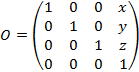 - the source object matrix;
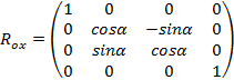 –
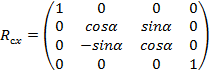
the object rotation matrix around the OX axis;
–
the object rotation matrix around the OX axis;
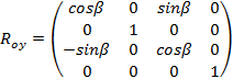 –
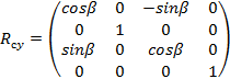
the object rotation matrix around the OY axis;
–
the object rotation matrix around the OY axis;
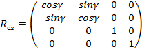
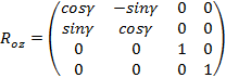 –
the object rotation matrix around the OZ axis.
–
the object rotation matrix around the OZ axis.
Then ![]() is a
matrix of the source object transformation,
is a
matrix of the source object transformation,
where ![]() .
.
Assume,
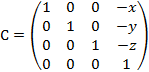 -
the camera position matrix;
-
the camera position matrix;
 –
the camera rotation matrix around the OX axis;
–
the camera rotation matrix around the OX axis;
 –
the camera rotation matrix around the OY axis;
–
the camera rotation matrix around the OY axis;
 –
the camera rotation matrix around the OZ axis;
–
the camera rotation matrix around the OZ axis;
Then ![]() is a
matrix of camera transformation, where
is a
matrix of camera transformation, where ![]() .
.
Let 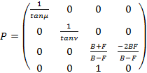 is
the perspective transformation matrix,
is
the perspective transformation matrix,
where
μ - an angle between the line going from the camera plane parallel to the z axis, and the right-hand edge of the viewport;
ν - an angle between the same line and the upper edge of the viewport;
F - a positive number defining the distance from the viewer to the front clipping plane at the object’s perspective projection to the viewport.
B - a positive number defining the distance to the back
clipping plane of the object. With that, B value can be infinite. Then, if ![]() , the following
conditions are met:
, the following
conditions are met:
(B + F) / (B - F) = 1;
![]() .
.
These conditions are true, if ![]() , because in this case
F value is deemed negligibly small as compared to B value, and therefore,
, because in this case
F value is deemed negligibly small as compared to B value, and therefore,
![]() , and
, and ![]() .
.
So, a final transformation of pixel coordinates may be written as follows.
![]() ,
,
where
 -
the column vector of initial coordinates of a pixel,
-
the column vector of initial coordinates of a pixel,
 -
the column vector of transformed coordinates of a pixel.
-
the column vector of transformed coordinates of a pixel.
The described algorithm will be hereinafter referred to as the modified Wu’s algorithm.
2.2. Comparison of the modified and standard Wu’s algorithms
Standard and modified Wu’s algorithms are compared for normal images with regard to two criteria (indicators): speed and quality of rasterization.
It should be emphasized that drawing a 45°-line segment raises maximum complexity. Hence, the algorithm speed is evaluated for a line segment with ({0;0};{n;n}) coordinates.
The modified Wu’s algorithm is linear, i.e. its speed depends on the number of raster points. Herewith, to draw each point, two runs are required. So, drawing a line segment with ({0;0};{n;n}) coordinates requires 2n iterations. Table 2 demonstrates results of the analysis. Here, the iteration complexity means either the number of operations for shading a pixel, or brightness per pixel.
Table 2. Speed and complexity of the modified Wu’s algorithm
|
Name of algorithm |
Number of iterations |
Complexity of iteration |
|
modified Wu algorithm |
2n |
2+о(2) |
As shown in Tables 1 and 2, the modified Wu’s algorithm is inferior to the standard one in the speed of operation.
However, case studies prove that the modified Wu’s algorithm outperforms the standard one in quality when photographs are taken at big angles from the normal. Fig. 9 illustrates the results.
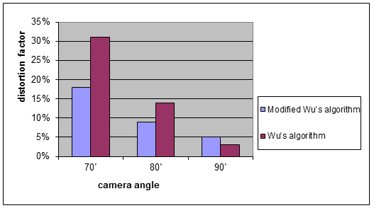
Fig. 9. Quality comparison for the modified and standard Wu’s algorithms.
3. Approbation of Wu’s algorithms
Wu’s algorithms under consideration are implemented in a prototype of the software complex RastWuCAD aimed to support construction of large objects.
The complex comprises a set of web-services such as a file navigator, photo player for objects under construction, a browser of geographic images.
RastWuCAD is a client-server application. The server side implements REST technology using Java, the client side - HTML+CSS+JavaScript and Flex (ActionScript). Server and client sides communicate via AJAX.
The file navigator supports standard file management features, such as viewing and creating folders, downloading and copying files, searching for files and folders. The file space contains mostly vector-based images of construction objects, digitized geographic Google maps - in a raster form.
The photo player allows for scaling images, viewing photographs of objects under construction, over time and at different angles.
The image viewer enables rasterization of vector images associated with file space objects and matches them to digital geographical maps provided by Google maps. The viewer lets users change object location on the map and transparency of their representation.
Fig. 10 depicts a screenshot of the viewer window where a construction object overlays the map. It is a plan of a cottage settlement with laid road communications. The vector-based image is built by AutoCAD, overlaying the place topography by means of RastWuCAD.
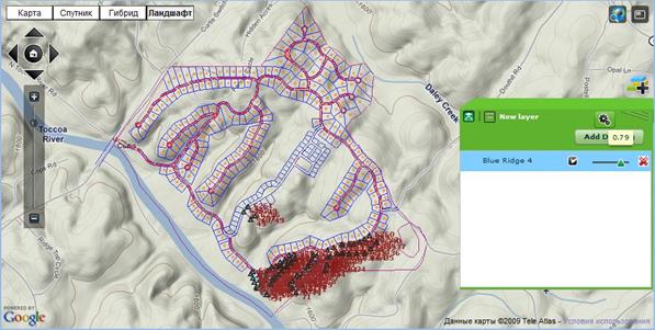
Fig. 10. Geographical objects viewer after overlaying the object on the map
Approbation of the modified Wu’s algorithm for rasterization of construction objects demonstrates that the distortion factor falls within the range from 3 to 17 %, which is a good result as per expert assessments.
Conclusions
Thus, we can make the following conclusions.
1. To address the rasterization task, we selected and studied Wu’s algorithm. Analysis of rasterization results shows that the algorithm is fast and allows for drawing high-quality smooth line segments.
The research also delineates that the algorithm provides poor quality in case of low-scale maps. Therefore, the standard Wu’s algorithm is recommended for rasterization of large-scale maps where higher priority is given to the speed of representation.
2. For the purposes of image rasterization and correlation with low-scale maps, the modified Wu’s algorithm has been developed. According to the study, it appears to be worse in rasterization speed as compared to the standard Wu’s algorithm. However, the approbation shows that it ensures higher quality in overlaying raster images onto oblique photographs.
Based on the general considerations, we assume that the modified Wu’s algorithm can be used in furtherance of vector image rasterization without sacrificing quality not only in the sphere of construction but in other subject areas. However, the present study does not serve this purpose and the above assumption needs experimental verification.
References
1. Bresenham J. E. Algorithm for computer control of a digital plotter // IBM Systems Journal. – 1965. – V. 4. – P. 25–30.
2. Y. Wu, "Raster, Vector, and Automated Raster-to-Vector Conversion", inMoving Theory into Practice: Digital Imaging for Libraries and Archives, Book Eds. by A.R. Kenney and O.Y. Rieger, 2000, Research Libraries Group
3. Ivanov D., Karpov A., Kuzmin E. Algoritmicheskie osnovy rastrovoj grafiki [Algorithmic fundamentals of raster graphics] [Electronic resource].Official site of Internet university of information technologies (www.intuit.ru). 23.04.2007. URL: http://www .intuit.ru/studies/courses/993/163/info, free. – The title from the screen. [in Russian].
4. Kulikov A., Ovchinnikova T. Algoritmicheskie osnovy sovremennoj komp'juternoj grafiki [Algorithmic fundamentals of modern computer graphics] [Electronic resource]. Official site of Internet university of information technologies (www.intuit.ru). 20.10.2007. URL: http://www .intuit.ru/studies/courses/70/70/info, free. – The title from the screen. [in Russian].
5. Rogers D. Algoritmicheskie osnovy mashinnoj grafiki [Algorithmic basics of machine graphics]. M.: World, 1989. 512 p.