TEXTURE COMPRESSION TECHNIQUES
T. Paltashev1, I. Perminov2
1 Advanced Micro Devices, Sunnyvale, CA, United States of America
2 University ITMO, St. Petersburg, Russian Federation
Timour.Paltashev@gmail.com, timour.paltashev@amd.com, i.am.perminov@gmail.com
Contents
Specifics of Texture Compression
BC6H and BC7 General Information
Bounded Integer Sequence Encoding (BISE)
Brief description of all discussed texture compression formats
In this paper, we present a detailed analysis and comparison of texture compression techniques and their hardware implementations used in modern PCs, tablets and smartphones, based on their characteristics, such as compression rates and image quality. First, we review the family of the earliest massively used compression schemes, the S3TC (BC1-BC3). Then, we move on to BC4, BC5, BC6H and BC7 formats, which improved the image quality by providing more flexibility as well as introducing block partitioning. We also analyze the mobile targeted ETC family (PACKMAN, ETC1 (iPACKMAN) and ETC2/EAC), developed by Ericsson, and the PVRTC family of formats, created by Imagination Technologies. Finally, we present ASTC, the latest texture compression technology resulted from a collaboration of AMD and ARM. BISE encoding and other features of ASTC are described in details.
Key words: computer graphics, texture compression, texture decompression, S3TC, DXT, BCn, BC6H, BC7, ETC, ETC2, EAC, PVRTC, PVRTC2, ASTC.
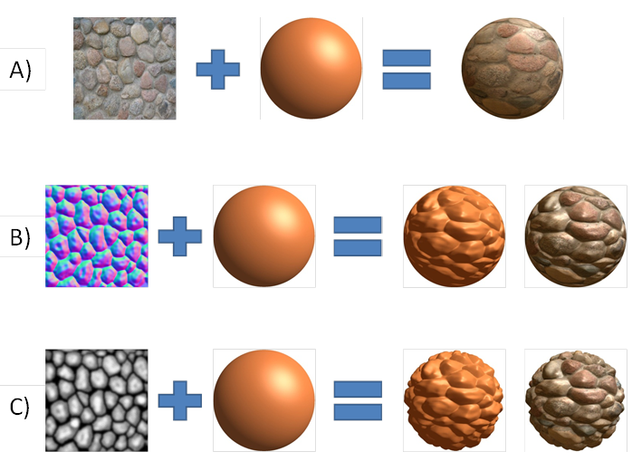
3D computer graphics is inconceivable without textures of various types. This greatly enhances visual quality and level of details of 3D objects without increasing geometry complexity. Simple textures are 2D images that map to 3D surface. Individual pixels of that image are called texels (texture element). Basically, textures can store not only colors but also heights, normal directions, specular factors and other per texel information (see Figure 1). Modern games and 3D applications consume a lot of memory, and more than half of that memory is occupied by textures (1). This leads to high requirements to both memory size and bandwidth. Various techniques of texture compression were widely adopted to reduce the pressure on the memory and bandwidth. In this case, textures are stored in memory and transferred to GPU in a compressed form. Unpacking only occurs inside GPU, usually between L1$ and L2$ caches. Such approach reduces textures memory footprint. Most important, that compression also saves bandwidth, which is a very valuable resource. Compression also reduces power consumption, because overall GPU↔VRAM traffic could be directly converted to expense of power. This is especially important for mobile devices such as notebooks, tablet PCs and smartphones.
Figure
1.
Examples of texture mapping for various types of textures.
A – diffuse map, B – normal map, C – displacement(height) map.
Specifics of Texture Compression
In most cases, texture is represented by a 2D image. However, standard compression algorithms (RLE, LZW, Deflate) and popular compressed image formats (JPEG, PNG, TIFF) are not suitable for textures. The main issue here is the absence of random texel access. Therefore, it is impossible to unpack a particular texel without unpacking the entire texture. Texture access pattern is highly random: only needed parts of texture are used during rendering and the order is not know in advance. Moreover, adjacency of triangles does not imply adjacency of corresponding texture regions (see Figure 2). Therefore, the overall performance of the graphics subsystem highly depends on the efficiency of the texture access. Random access determines main characteristics of various texture compression formats.
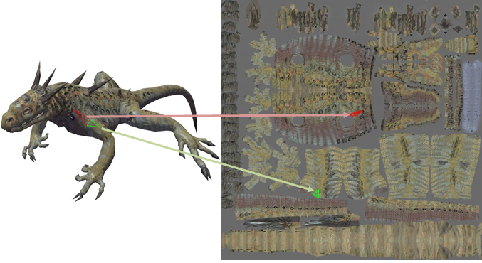
Figure 2. Example of texture layout. (Texture and 3D mesh source: Microsoft DirectX 9 SDK).
Most of the texture compression schemes divide the entire image into blocks of a fixed size called tiles, which are compressed individually. Nevertheless, some formats, for example PVRTC, are exceptions to this rule. The following factors are important and should be considered when evaluating a texture compression scheme:
•Random access. GPU needs to be able to access efficiently to any random texel. Therefore almost all known compressors have a fixed-rate compression. This, in turn, obviously means lossy compression. Nevertheless, non-fixed rate schemes that could satisfy random access requirement are still possible. For example, Inada and McCool in (2) propose lossless variable-rate scheme where high performance is achieved by modification of the texture cache architecture.
•High decompression speed. Texture access time is a critical factor affecting the overall performance of the graphics subsystem. This implies the following two factors:
oLow cost hardware implementation of the decoder. The decoding algorithm should be relatively simple. So wavelet and discrete cosine transformation (DCT) are rarely used.
oNo indirect and chaining memory access. Ideally, only one memory read have to be done to get all the information necessary to decode a small texture region. Minimal additional reads have to be done to get filtered texture data. Any additional memory access (such as reading color palette or other tables) increases the overall latency. Indirect access also reduces cache efficiency because of the reduced locality.
•High compression ratio. This is the main factor that determines how much of the bandwidth would be saved during texture fetch operations. The compression ratio is usually expressed in either the bit rate or the average number of bits per texel (bpp). Typical bpp values are from 2bpp to 8bpp.
•The image is divided into blocks of small size, usually 4x4 texels. Smaller blocks are harder to compress. On the other hand, larger blocks can affect the cache hit-rate. It is also desirable that the size of the compressed block was smaller than the width of the memory bus in order to reduce the delay and simplify the hardware implementation. If a compressed block occupies the same number of bits as the bus width, then pipeline stalls can be avoided (3). Modern graphics processors in PCs have memory bus width ranging from 64 to 512 bits. Due to strict hardware and power budgets, texture compression schemes for mobile devices utilize a very high compression ratio (2bpp) or smaller blocks to fit into the memory bus width.
•Acceptable visual quality of decompressed texture. It is obvious that the distortion introduced by the compressor should be as small as possible.
In this article, we will discuss in detail only the formats that provide random access and have hardware support. However, streaming texture compression should be mentioned as well. It is used to speed up loading of textures to VRAM from disk or over network. It is an issue for the modern applications where the size of texture data has an order of gigabytes.
The main goal is to minimize the size of the data. Absence of random access requirement allows one to achieve very high compression ratios and/or lossless compression. After such textures loading into the memory, programmable shaders are used to unpack it. The result could be either an uncompressed or a compressed texture in one of hardware-supported formats. It is also possible to conduct memory management in the following manner: keep a complete set of textures in VRAM in a highly compressed form, and a subset of textures for current scene in GPU-friendly format.
Compared to the commonly used compression methods (RLE, LSW, Deflate) this specialized approach gives better compression ratio. In case of game consoles, this technique allows developers to put more content on one optical disc.
For example, the Virtual Texturing technology used in the IdTech5 engine (4) can load and transcode textures on the fly from JPEG-like format to DXT. However, the final texture will contain compression artifacts introduced by both formats.
Among the other publications, we should mention Olano et al. (5) where lossy and lossless compression schemes tightly coupled with mip-maps are proposed, and Ström et al. (6) where lossless compression of ETC-compressed textures is described.
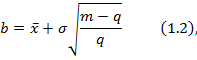
While the difference between the original and the reconstructed image is largely determined by the compression format, the compression algorithm plays a significant role as well. Clearly, exhaustive search based algorithms produce the best quality at the cost of performance. Achieving decent quality at a reasonable speed is a non-trivial task for the majority of compression formats. As follows from the above, it is essential to specify in detail how the compression is made and which algorithm is used, when comparing the quality of compressed textures.
Decompression algorithm can also affect the image quality. For example, the hardware implemented DXT1 decoder in GeForce/GeForce2 chips perform all internal operations with colors in 16-bit mode, without converting to 24 bits (7). This leads to additional artifacts when unpacking (see Figure 3).
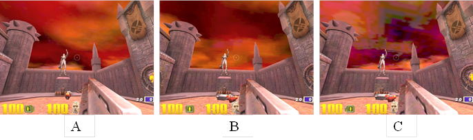
Figure
3.
Compression artifacts. A – uncompressed, B – DXT1 on S3 Savage2000,
C – DXT1 on NVidia GeForce 256 (Source: iXBT (7))
The traditional approach in real time 3D graphics is to use pre-compressed textures, which are produced by offline compressor. Modern rendering engines, however, increasingly often utilize a lot of dynamically generated data like environment maps for reflection simulation, G-buffer in deferred shading etc. This makes online texture compression (when textures are compressed on every frame) valuable. Online compression is also used in low-latency high resolution video streaming, like UltraGrid (8) (9).
Although fast compression algorithms for some formats already exist (10) (11) (12), compression of dynamically generated data requires new approaches because of hardware limitations.
For example, a pixel shader cannot access any neighboring pixels. Due to possible pixel overlap, the final version of the tile is only available once the frame rendering is complete. One way to overcome these limitations is to use tile-based GPU architecture. Although the texture can also be compressed after it is sent into the VRAM, data copying overhead introduced by the current 3D APIs (both Direct3D 11.2 and OpenGl 4.4) significantly reduces the efficiency of this approach (13).
In this article, we will discuss some of the most known texture compression formats in more detail:
•the S3TC family, used in PCs
•the ETC and PVRTC families, designed for mobile devices
•and ASTC, the new format applying to all platforms
In the simplest case, pixel may be encoded by a single number (using usually 4 or 8 bits) representing an index in color palette. Such technique was widely used for reducing the size and the memory bandwidth of the video framebuffer in the early video adapters and game consoles. However, the color palette approach is not suitable for texture compression due to the following shortcomings:
•Low compression ratio (typical bit rate is 8bpp)
•Poor quality due to the limitation of the number of unique colors (256 colors at 8bpp)
•Double memory access (reading texel value, then reading color palette) increases the latency and consumes additional bandwidth. Although the memory for color palette could be implemented as a dedicated RAM, it would still be necessary to rewrite the palette each time a new texture is accessed.
Palette compression is a special case of VQ (Vector Quantization) with the vector being a single pixel. A more complex version of VQ-compression used in Sega Dreamcast game console (14)resulted in an acceptable texture quality at the compression ratios of 1:5 and 1:8.
Block compression, an alternative approach, employs compression of fixed size blocks. Since each compressed block contains all the information necessary to decode whole tile, decoding could be done in a single memory read.
One of the first block compression schemes was Block Truncating Coding (BTC), intended for compression grayscale images. The main idea of the algorithm is to preserve sample moments: mean and variance. It is achieved by using only two different values "a" and "b" in each reconstructed tile (see Figure 4). A compressed block consists of these two values and a bitmap, where each bit corresponds to one texel.
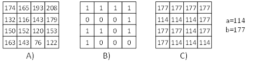
Figure 4. BTC encoding example. A – source block, B – bitmap, C – decoded block.
The BTC encoding
is done is several steps. First, an image is divided into blocks of MxN texels
(typically 4x4). Then the mean value ![]() and
the standard deviation
and
the standard deviation ![]() are
calculated for each block. Next, the bitmap is constructed: a bit is set if the
corresponding texel value is greater than the mean. Finally, the “a” and “b”
values are calculated according to formulas 1.1 and 1.2, preserving the mean
and the variance of the block.
are
calculated for each block. Next, the bitmap is constructed: a bit is set if the
corresponding texel value is greater than the mean. Finally, the “a” and “b”
values are calculated according to formulas 1.1 and 1.2, preserving the mean
and the variance of the block.
where m is the number of texels in the block, and q is the quantity of "1" in the bitmap.
BTC features simple encoding and a trivial decoding algorithms, as well as a good compression ratio of 1:4 or 2bpp for a 4x4 tile. The BTC algorithm was used for compressing Mars Pathfinder's rover images (15).
For color images, one can apply the BTC algorithm separately to each color channel, resulting in a compression level of 6bpp. However, this scheme greatly reduces the quality of the final image (see Figure 5). BTC-based approach called Color Cell Compression (CCC) offers 2bbp or 3bpp. Similar to BTC, all values in CCC are quantized to two levels, but only one bitmap is using for all three channels.
Figure 5. Images compressed with BTC. Original on top, decompressed on bottom.
The encoding
algorithm of CCC is similar to that of BTC. At the first step of compression, texel-wise
luminance ![]() and
the average block luminance
and
the average block luminance ![]() are
computed (see equation 1.3). Then, the bitmap is constructed by comparing the
luminance of the texel to the average luminance. At the last step, basic colors
"a" and "b" are chosen.
are
computed (see equation 1.3). Then, the bitmap is constructed by comparing the
luminance of the texel to the average luminance. At the last step, basic colors
"a" and "b" are chosen.
![]() (1.3)
(1.3)
There are two variations of CCC. In the first one, base colors a and b are directly stored in the compressed block in RGB565 format, which gives 48 bits block (16 bits for each base color and 16 bits for bitmap) and compression level of 3bpp. In the second variant, 8-bit palette indexes are stored instead of the base colors, resulting in a compression level of 2bpp. This version of CCC also suffers from palette compression drawbacks.
While providing high compression rates and simple hardware implementation, CCC results in a low quality image, since only two unique colors are used within a block. Nevertheless, the main ideas of CCC are used in the modern formats of texture compression, that we will discuss later.
S3TC (S3 Texture Compression) was originally developed and patented by S3 Incorporated (16) . Introduced in 1999, S3TC has been widely accepted as the industry standard and still it is one of the most common compression schemes. Microsoft adopted S3TC in their 3D API DirectX 6.0 under the name DXT1. Its modification for textures with alpha channel became known as DXT2-DXT5. All together, these formats are often named DXTC (DirectX Texture Compression). DXT1 is also supported in OpenGL and OpenGL ES via the EXT_texture_compression_dxt1 (17) specification extension. This extension is a part of EXT_texture_compression_s3tc (18) , which also describes DXT3 and DXT5.
Starting from DirectX 10, these formats are called BC1-BC3 (Block Compression). Two new formats were added, BC4 and BC5, which were earlier known as ATI1/3Dc+ and ATI2/3Dc. Appearance of 3Dc format was dictated by the necessity of normal map compression. DXT1 is designed for color data and is not efficient at compressing normal data. BC4 and BC5 functional specified in OpenGL extensions EXT_texture_compression_rgtc (19), ARB_texture_compression_rgtc (20) and EXT_texture_compression_latc (21).
With the release of DirectX 11, two additional formats were presented: BC6H, the first standard format aimed at high dynamic range (HDR) textures, and BC7, designed for very high quality compression. On the OpenGL side, both formats are described in the ARB_texture_compression_bptc (22) specification.
All S3TC family formats use 4x4 blocks. We will describe these compression formats in the next subsections.
Likewise the CCC, the BC1 block consists of two base colors c0 and c1 and an index table (bitmap) (see Figure 6). The index table, however, has a two-bit entry, since BC1 allows for 2 additional colors, c2 and c3 obtained by blending of the base colors. All together c0, c1, c2 and c3 could be treated as a local palette for a compressed block. The presence of four different colors significantly increases the image quality in comparison to CCC. The base colors are stored in RGB565 format, i.e. 5 bits for red and blue channels and 6 bit for green channel, resulting in 4bpp compression level.
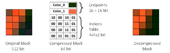
Figure 6. BC1 block example.
There are two types of BC1 blocks: the first one that doesn’t support transparency and the second one, that does.
For the first type, there are two ways to define c2 and c3. In most implementations, they are calculated according to the equation 2.1, which represents a 1:2 and a 2:1 linear blend. If we assume that the color values inside a block are normally distributed, then the equation 2.2 will give a lower error. This approach is used in nVidia GPUs (23). Moreover, hardware implementation of RGB565 to RGB888 color conversion may have some simplifications, which also affects the outcome. Therefore, the same compressed data could produce different result on different hardware. In both cases, the four colors lie on the same segment in the RGB space, with c0 and c1 as its endpoints.
![]()
![]() (2.1)
(2.1)
![]()
![]() (2.2)
(2.2)
The second type of BC1 allows one to encode a one-bit alpha channel that can be used for textures with simple transparency. Each texel can only be either completely transparent or completely opaque. Such mode is also known as a punch-through alpha. For this type of BC1 blocks, c3 is computed as a 1:1 linear blend (equation 2.3) and c2 represents the full transparency. Besides, some tiles of original image without transparent texels can be more accurately encoded with blocks of the second type.
![]() (2.3)
(2.3)
In the naive implementation, one additional bit is needed to distinguish between blocks of the first and the second types, but in practice it's done using data redundancy, since the same block could be encoded by swapping endpoints and recomputing indices. In this way, if c0 (interpreted as a 16-bit integer) is greater than c1, the block is decoded as the first type block. All other blocks are blocks of the second type.
Selection of endpoints has a strong impact on quality. Finding appropriate endpoints, which give minimal error, is challenging. There are many different codecs aimed at speed (10) (11) (24) or at high quality (25).
In 2004, nVidia has presented an NV_texture_compression_vtc extension for OpenGL (26), with added support for 3D-texture compression with block sizes of 4x4x1, 4x4x2, 4x4x3 or 4x4x4. However, this extension did not provide any novel approaches for compression; a VTC block consists of 1, 2, 3 or 4 independent S3TC/BC1 blocks, each of which encodes a two-dimensional 4x4 slice.
The BC1 format can manage 24-bit RGB textures, but is unsuitable for 32-bit RGBA8888 textures. Alpha channel can be used to store transparency, specular data or other properties of a material. The BC2 and BC3 Direct3D formats are designed for such textures. The BC2 block occupies 128 bit, twice the BC1 size. Therefore, compression level is 8bpp. One half of the BC2 is reserved for alpha values with 4-bit precision (“alpha a” through “alpha b”), the other one is just a BC1 for storing RGB data (see Figure 7). Actually, BC2 conforms to RGBA8884 texture with compressed RGB-channels. Color channels are decoded in the same manner as in case of BC1. The only difference is that it always treated as a block of the first type.
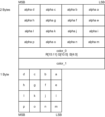
Figure 7. BC2 block layout. (Source: Programming Guide for Direct3D 10 (27))
To perform compositing or blending with the background in the case of translucent textures, color values must be multiplied by transparency factor from the alpha-channel. In this regard, it is convenient to store already premultiplied values in the color channels. The DXT2 format is proposed for such cases. The DXT3 block layout coincides with DXT2, but the color values assumed not to be premultiplied. Nevertheless, decoding procedures for DXT2 and DXT3 are all the same. Format names are only used as a hint about the meaning of the color data. Therefore, BC3 format does not differentiate between such cases, and the application is responsible for interpretation of the data.
It is important to note, that color values should be always multiplied by alpha before performing texture filtering. Otherwise, filtered result would not be correct. The premultiplied alpha mode has certain advantages over storing initial values in the case of alpha-blending and can be used for simplifying the hardware. Details on premultiplied alpha can be found in «Jim Blinn's Corner: Compositing, Part 1: Theory» (28).
The BC3 block, likewise BC2, consists of two 64-bit parts: one for the alpha data and one for the color data. Color part repeats the BC1 layout as well, but the alpha part is stored in the compressed form (see Figure 8). Alpha compression is very similar to the DXT1 except for the number of the channels; there are two endpoints with 8-bit precision and the table of 3-bit indexes allowing to choose one of the eight values of a local palette.
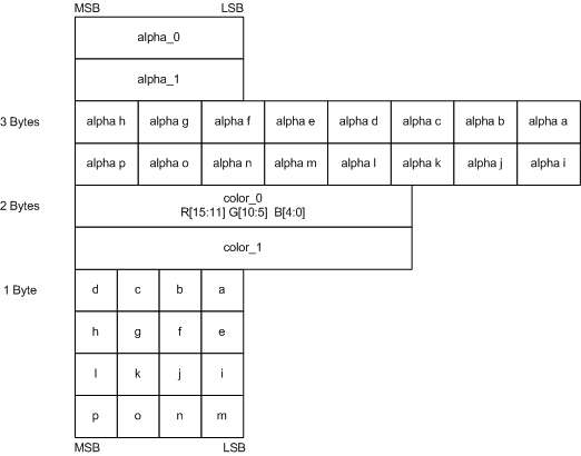
Figure 8. BC3 block layout. (Source: Programming Guide for Direct3D 10 (27))
The same data redundancy trick as in BC1 is applied to specify the decoding mode. If alpha_0 > alpha_1, six additional values of the local palette are calculated by linear interpolation. Otherwise, only four values are interpolated, and remained two corresponds to the maximum and the minimum allowable values. Alpha channel’s palette population is shown in the Listing 1. BC1 sub-block is always treated as a block of the first type and equations 2.1 or 2.2 are applied.
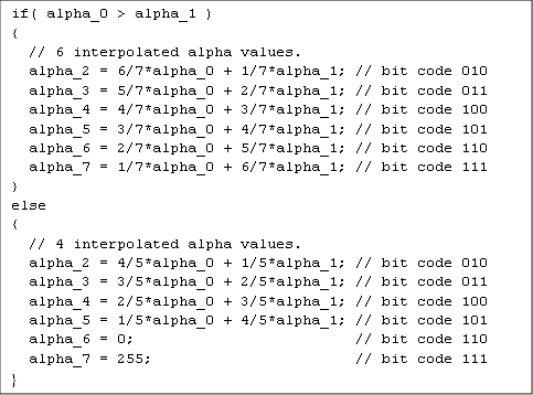
Listing 1. Palette population for alpha channel. (Source: Programming Guide for Direct3D 10 (27))
Similarly to DXT2/DXT3, DXT4/DXT5 formats in Direct3D 9 differ only in the meaning of the color channel data. DXT4 assumes that the stored color data is premultiplied by the alpha, and DXT5 assumes that it is not. There is only one BC3 format in Direct3D 10, which does not distinguish between these two cases.
Usually, BC3 format provides better quality than BC2, which should be used for low-coherent alpha data.
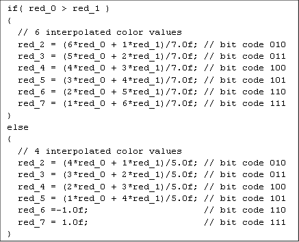
The BC4 block (Figure 9) is just an alpha part of the BC3 block. It is used for 1-channel textures, for example a height map or a specular map. Decoded values are associated with the red channel.
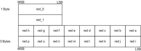
Figure 9. BC4 block layout. (Source: Programming Guide for Direct3D 10 (27))
Listing 2. Palette population for BC4 block. (Source: Programming Guide for Direct3D 10 (27))
The decoding of a BC4 block is performed in the same manner as the decoding of a BC3 alpha part. However, 1-channel data (a displacement map, for example) is usually more convenient to represent using float point values in the range [0, 1] or [-1, 1]. Therefore, endpoints red_0 and red_1 are interpreted accordingly. Palette population for the [-1, 1] case is shown in Listing 2.
The 3Dc format was originally developed by ATI specially for the normal map compression, as the DXT1 format did not provide the required quality for such data. Normal map contains information about the direction of normal vector for every texel, which allows one to compute lighting with high level of detail and without increasing the geometry complexity (see Figure 1.B). Coordinates of a normal vector are stored in the color channels and these values are interpreted as floats in [-1, 1] range. The problem of the BC1 compression is that the values of different color channels are coupled together via shared index table. It is appropriate for regular RGB images, but not for normal maps, where the channels are uncorrelated. Also, BC1 significantly restricts the gradient values due to a small local palette size. For these reasons, normal maps compressed with BC1 have poor quality (see Figure 10).
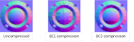
Figure 10. Normal map compression. (Source: ATI 3Dc White Paper (29))
By definition, normal vectors have a unit length, so they can be specified by x and y coordinates only, and the z can be computed using the equation 2.4. In the case of tangent space normal vectors (24), the sign of z is always positive.
![]() (2.4)
(2.4)
The BC5 block is just a double BC4. That allows to store two channels independently (see Figure 11). This fact coupled with a larger local palette of BC5, results in a superior image quality for 2-channel textures compared to BC1.
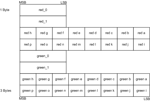
Figure 11. BC5 block layout. (Source: Programming Guide for Direct3D 10 (27))
Decoding procedure of each sub-block is exactly the same as that of BC4 decoding. The z coordinate isn’t computed by default, as the BC5 format can be used for any two-component textures and the decoded values fill the red and green channels. In case of normal maps, missing Z coordinate can be calculated in a pixel shader.
Corresponding OpenGL extensions are called EXT_texture_compression_rgtc (19), ARB_texture_compression_rgtc (20) and EXT_texture_compression_latc (21). The _rgtc and _latc versions of specification describe both 1-channel BC4 block and 2-channel BC5 block. In the case of _rgtc, unpacked data are interpreted as values of the red and green color channels. In the case of _latc, unpacked data are interpreted as values of luminance or luminance and alpha.
BC6H and BC7 General Information
The main factors limiting BC1 compression quality are:
•Low precision of the endpoints (RGB565). Moreover, uneven distribution of bits across the channels may cause a color shift. For example, many pure grey colors cannot be “purely” represented in RGB565: RGB565(12, 24, 12) is RGB888(99, 97, 99) which is slightly purple, but RGB565(12, 25, 12) is too greenish RGB888(99, 101, 99).
•Small size of the local palette. Only 4 different colors can be used in one block.
•All colors lie on the same line in RGB space. If the colors in the original block do not map to a line segment, the compressed block may look pretty bad (see Figure 12).
Figure 12. BC1 “bad” block compression example
These problems are solved in the new formats by improving the endpoint precision and storing up to three pairs of endpoints. Both formats use 128-bit blocks, resulting in 8bpp compression level. Depending on the block type, a compressed block has a different set of fields and a different size of each field. This allows choosing the best encoding on the per block basis. This flexibility greatly reduces compression artifacts, but strongly complicates the compression procedure. The number of block types has increased to 14 for BC6H and to 8 for BC7. Unlike BC1, block type is set explicitly in the first bits of compressed block. Block type is also referred to as the block mode.
To employ multiple endpoint pairs, a tile is divided into groups of texels called subsets. Each subset has its own endpoint pair. There are 64 predefined partition sets for two-region tiles and 64 partition sets for three-region tiles. Thus, only partition ID should be stored in compressed block to specify particular partitioning. Some of these partition sets are shown in Figure 13.
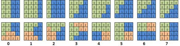
Figure 13. The first eight partition sets for two and three-region tile.
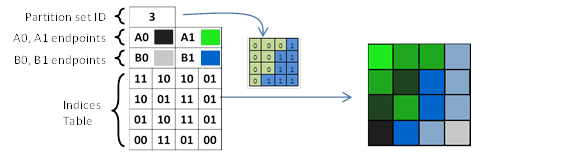
Figure 14. Simplified example of BC6H/BC7 block decoding for two-region tile.
As in previous formats, the values from index table specify the proportions in which the endpoints are blended. The partition ID determines which endpoint pair is used for each texel. Simplified decoding example is shown in Figure 14, where A0-A1 and B0-B1 endpoint pairs are used for subsets 0 and 1 respectively. The size of an index may be from 2 to 4 bits. Thus, the number of intermediate colors available in each subset ranges from 2 to 14.
An important feature of the BC6H and BC7 formats is the requirement of bit-accurate decoding. The hardware must return results, identical to the reference decoder, even for invalid blocks. Detailed information about all block modes can be found in Direct3D 11 documentation (30) and in OpenGL ARB_texture_compression_bptc extension specification (22). This specification is a part of OpenGL Core Profile since OpenGL 4.2 (31).
The DXT1 format did not specify the interpolation (blending) procedure; different hardware uses different weights (see BC1 Block (S3TC/DXT1)). Interpolation in the new formats is always performed using a factor 64 and interpolation weights are strictly defined. The pseudo code for BC7 interpolation is shown in Listing 3, where indexprecision is a bit size of an individual index and could be 2, 3 or 4 (bits).
![UINT16 aWeight2[] = {0, 21, 43, 64};
UINT16 aWeight3[] = {0, 9, 18, 27, 37, 46, 55, 64};
UINT16 aWeight4[] = {0, 4, 9, 13, 17, 21, 26, 30, 34, 38, 43, 47, 51, 55, 60, 64};
UINT8 interpolate(UINT8 e0, UINT8 e1, UINT8 index, UINT8 indexprecision)
{
if(indexprecision == 2)
return (UINT8) (((64 - aWeights2[index])*UINT16(e0) + aWeights2[index]*UINT16(e1) + 32) >> 6);
else if(indexprecision == 3)
return (UINT8) (((64 - aWeights3[index])*UINT16(e0) + aWeights3[index]*UINT16(e1) + 32) >> 6);
else // indexprecision == 4
return (UINT8) (((64 - aWeights4[index])*UINT16(e0) + aWeights4[index]*UINT16(e1) + 32) >> 6);
}](files/image030.png)
Listing 3. Interpolation
procedure used in BC7 decompression.
(Source: Programming Guide for Direct3D 11 (30))
Without going into details, the interpolation procedure for BC6H is almost the same, except it uses signed values.
In DXT1, data redundancy was used for encoding the block type. In BC6H/BC7, the same trick is used for reducing the size of index table; each endpoints pair encodes one bit. For example, consider the index of texel 0, which is upper left texel. If its highest bit is 1, then it is possible to swap corresponding endpoints and this bit becomes 0. Thus, it is always possible to rearrange endpoints so that the highest bit of one certain index in that subset would be 0. Such indexes are called anchor indexes and its highest bit is never stored in the compressed block. Index for texel 0 is always anchor index of subset 0. Location of anchor indexes for some partition sets is shown in Figure 15.
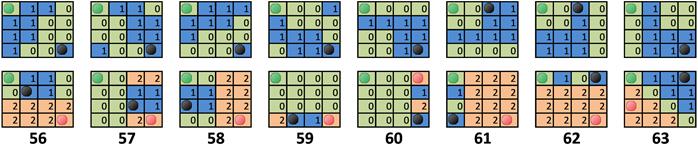
Figure 15. The anchor index position for some two and three-region tiles.
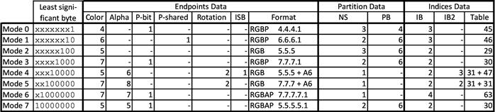
Table 1. Sizes of BC7 block fields for each of the block modes.
Table 1 shows sizes (except the NS and Format columns) of different bitfields for all BC7 block modes:
•Color – size in bits of each color channel
•Alpha – size in bits of alpha channel
•P-bit – P-bit presence
•P-shared – shared P-bit presence
•Rotation – size in bits of “Rotation” field
•ISB – presence of idxMode/ISB (Index Selection Bit)
•NS – number of subsets
•PB – size in bits of partition index
•IB – size in bits of index in indices table
•IB2 – size in bits of index in secondary indices table
•Table – total size in bits of indices tables
Block mode in Table 1 is specified as a value of LSB byte with lowest bit on the right. On the further figures taken from Direct3D 11 MSDN page (30) mode field is shown with the lowest bit on the left. Thus, the values are reversed.
The PB field in BC7 Mode 0 block has only 4 bits (see Figure 16). Therefore, only first 16 partition sets can be used. In the other multiple subsets modes all 64 partition sets are available.
The new field "P-bit" and the meaning of the appropriate letter in RGBP/RGBAP abbreviations can be explained by the example of the BC7 Mode0 block (see Figure 16). There are three RGB444 endpoint pairs stored in the block and one P-bit for each of the endpoints. Before unquantization, each endpoint is extended to RGB555, where the same P-bit is used as the lowest bit of all channels. In comparison with storing directly RGB555 color, this approach allows to save 2 bits for each endpoint, but the loss of precision does not exceed 1 bit (only one or zero bits would be distorted in all color channels).
BC7 Mode 1 uses a P-shared bit. It is similar to P-bit, but its value shared between both endpoints in a pair.
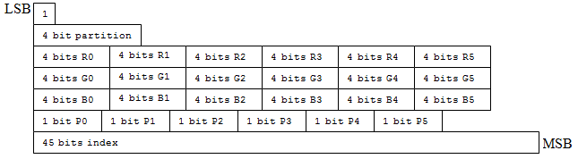
Figure 16. BC7 Mode 0 block layout. (Source: Programming Guide for Direct3D 11 (30))
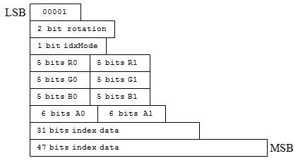
Figure 17. BC7 Mode 4 block layout. (Source: Programming Guide for Direct3D 11 (30))
BC7 Mode 4 (see Figure 17) and BC7 Mode 5 blocks have two independent index tables, allowing to save one of the four channels separately. It is suitable for textures, like normal maps, where one of channels does not correlate with the others. These modes can be used to store color and alpha values separately, similarly to BC3. However, it is possible to save any channel with its own index table. "Rotation" field is used to determine which channel would have independent table.
In BC7 Mode 4 block, these index tables have different bit sizes and therefore different index precision. The ISB field (shown as idxMode in Figure 17) determines which of these tables will be used for independent channel and which for remaining coupled channels.
The BC6H format is designed to compress textures with high dynamic range, or HDR (32). Only RGB images without alpha are supported. Values are represented in a 16-bit floating point format, signed or unsigned. Therefore, a decoder can operate in signed or unsigned modes. Nevertheless, decoded values are always signed half floats and conform to the IEEE 754 half/binary16 format (see Figure 18A). After decoding, values are returned to the shader as a 32-bit float. All block modes are identical for signed and unsigned versions of BC6. Conventionally, the internal representation corresponds to Figure 18A for signed version, and to Figure 18B for unsigned. In practice however, only integer arithmetic is used for decoding. Signed/unsigned decoding modes differ in the sign bit handling during color unquantization.
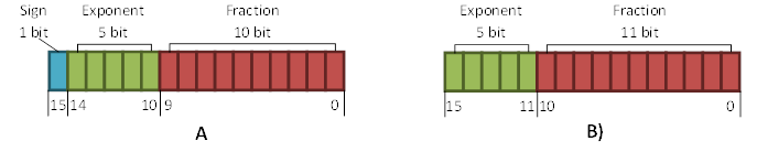
Figure 18. 16-bit precision floating-point formats. A – signed, B – unsigned.
There are 14 block types (see Table 2). BC6H supports only one- or two-region tiles. PB field (Partition ID) is always 5 bit. Thus, only first 32 partition sets are available. In most cases (except for the Modes 10 and 11), endpoints are stored using delta encoding: one endpoint stored directly, and the offsets are stored for all the remaining endpoints.
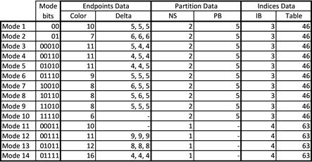
Table 2. Sizes of BC6H block fields for each of the block modes.
As previously mentioned, only integer arithmetic is used for decoding and interpolation, even though the final values are interpreted as floats. It works due to the float number encoding (see Figure 18), where biased exponent resides in high bits and mantissa (with implied "1") in low bits. Interpretation of such binary encoding as an integer makes a certain math sense. In particular, adjacent floats have adjacent integer representations. Moreover, for any positive A and B, such that A>B, their binary representation interpreted as integers will also give A>B. The example of integer arithmetic on floats is shown in Listing 4. When linear interpolation is used for integer representation of floats with different exponents, the resulting transformation will have an exponential (logarithmic) behavior (see Figure 19).
Listing 4. Example of integer operations on floats.
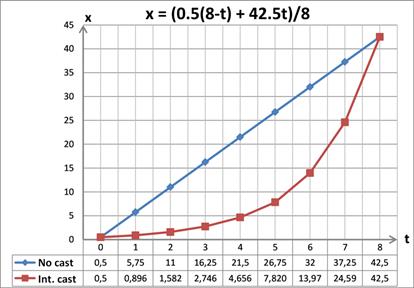
Figure 19. Interpolation
example. “No cast” – linear interpolation of floats,
“Int. cast” – casted to float linear interpolation of integer representation.
The decoding procedure consists of four stages:
•Sign extension and delta transform inversion. In case of a signed BC6H, all endpoints and offsets (deltas) stored in a compressed block are sign extended (sign bit is propagated to upper bits), in case of an unsigned BC6H, only offsets are sign extended. Furthermore, for all block types, except Mode 10 and Mode 11, the remaining endpoints are restored by adding the corresponding offset value to the directly stored endpoint. In Mode 10 and Mode 11 blocks, all endpoints are stored directly.
•Unquantization of the color endpoints. For unsigned BC6H, unquantization looks like (((X << 16) + 0x8000) >> uBitsPerComp), where uBitsPerComp is the bit size of one component of the directly stored endpoint. Boundary cases (zero, max value) are considered separately.
•Linear interpolation is performed akin to BC7 case. Given the existence of signed and unsigned formats, the full range of unquantized values are from -32768 to 65535. Therefore, the interpolator is implemented using 17-bit signed arithmetic.
•Final adjustment or final unquantization. Since maximum value of an exponent field (all ones) is used in IEEE 754 to encode special INF/NaN values, the interpolated values are scaled by 31/32 for signed format, and by 31/64 for unsigned format. The resulting value is a legal 16-bit half float.
The ETC (Ericsson Texture Compression) format was originally developed for use in mobile devices. Today, it is a standard compression scheme for Android based devices. ETC1 format is supported in OpenGL ES and WebGL via (33) and WEBGL_compressed_texture_etc1 (34) extensions. ETC1 and ETC2 specifications are the part of OpenGL Core Profile since OpenGL 4.3 (35).
The first version of the compression scheme, PACKMAN, was introduced in 2004 (3). Later, in 2005, the enhanced version called iPACKMAN was presented (36). This version is better known as ETC1 and is widely used in mobile devices. Subsequent development of this compression scheme resulted in appearance of the ETC2 format in 2007 (37).
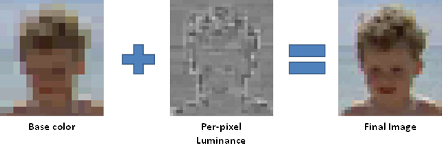
Figure 20. The core idea of PACKMAN. (Source: ETC2 Paper (37))
The main idea of ETC compression is based on a well-known fact about color perception, that humans eye is more sensitive to luminance rather than to chrominance. Accordingly, only one base color is stored in each sub-block (ETC1/ETC2 consists of two sub-blocks), but luminance information is stored on a per-texel basis (see Figure 20). The luminance offset is set by a single integer value, which is added to all color components. Only four different luminance offsets are available inside a sub-block, so only four different colors are available. These colors can be treated as a local palette.
Corresponding patents on ETC1 (38) (39) and ETC2 (40) (41) belong to the Swedish company Ericsson (Telefonaktiebolaget L. M. Ericsson).
If a compressed block occupies the same number of bits as the bus width, then pipeline stalls can be avoided, which simplifies hardware implementation (3). As mobile devices are strictly limited in memory sizes and bus widths, it was considered to use 2x4 tiles for PACKMAN. As the result, the compressed block occupies only 32 bits. Thus, the compression level is 4bpp, which is equal to that of BC1.
Only one RGB444 base color is stored in a block. Other colors are obtained by changing texel’s luminance. While basic idea is far from BC1, decoding process is very similar. At first, the four-color local palette is restored. Then, the index table is used to pick the colors from this palette (see Figure 21). However, because of the small block size there are only 4 bits to specify luminance variation and three additional colors in palette. Therefore, these 4 bits are used to encode one of the predefined luminance sets (see Table 3).
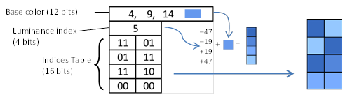
Figure 21. PACKMAN block decoding example.
|
Index |
0 |
1 |
2 |
3 |
4 |
5 |
6 |
7 |
|
Luminance 00 |
2 |
4 |
6 |
12 |
8 |
19 |
28 |
42 |
|
Luminance 01 |
8 |
12 |
31 |
34 |
50 |
47 |
80 |
127 |
|
Luminance 10 |
-2 |
-4 |
-6 |
-12 |
-8 |
-19 |
-28 |
-42 |
|
Luminance 11 |
-8 |
-12 |
-31 |
-34 |
-50 |
-47 |
-80 |
-127 |
Table 3. First half of the luminance codebook for PACKMAN
Clearly, the bottom half of the Table 3 is the negation of the top half, simplifying the decoder. Luminance sets 8-15 (not shown in the table) are equal to the 0-7 sets scaled by a factor of two. The table values were created by starting with random values and then optimizing them by minimizing the error for a test image (3).
A single low precision (RGB444) base color was the main quality limiting factor in PACKMAN. This issue was addressed in ETC1.
The size of an ETC1 tile is 4x4, and it consists two sub-blocks, as in a PACKMAN block. These sub-blocks can be arranged vertically or horizontally. That gives more flexibility for a base color choice inside a tile. Precision was enhanced by introducing a Differential block type, where a base color for the first sub-block is stored with RGB555 precision, and 3-bit differences are stored for the second base color. A block, where both base colors are stored directly in RGB444 format, is called Individual (see Figure 22).
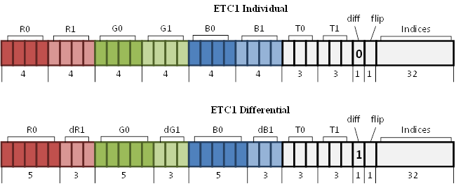
Figure 22. ETC1
block layout.
|
N |
0 |
1 |
2 |
3 |
4 |
5 |
6 |
7 |
|
Luminance 00 |
2 |
5 |
9 |
13 |
18 |
24 |
33 |
47 |
|
Luminance 01 |
8 |
17 |
29 |
42 |
60 |
80 |
106 |
183 |
|
Luminance 10 |
-2 |
-5 |
-9 |
-13 |
-18 |
-24 |
-33 |
-47 |
|
Luminance 11 |
-8 |
-17 |
-29 |
-42 |
-60 |
-80 |
-106 |
-183 |
Table 4. The luminance codebook for ETC1 and ETC2
To reserve the space for the block type encoding, luminance codebook was decreased to eight sets, so index size (T0 and T1 on Figure 22) drops to 3 bits. Obviously, the values in codebook were also recomputed (see Table 4). This frees 2 bits. One of them, "diff", specifies block type, and another, "flip", specifies vertical or horizontal arrangement of the sub-blocks.
The differential mode and the possibility to rotate sub-blocks have significantly improved the quality. However, only one base color is available in each sub-block and tiles with high chrominance variation are compressed with high errors. Moreover, even smooth gradients can also be problematical for ETC1.
ETC2 addresses these problems by introducing extra block modes. These new modes are encoded using blocks, which are invalid in the ETC1 scheme, making the ETC2 decoder fully compatible with the ETC1 format. Invalid combinations occur in a Differential block, when the sum of the base color and the offset overflows the valid 5-bit range [0, 31]. Such blocks are decoded using one of new modes. All combinations of R0 and dR1 that causes an overflow are shown in Table 5.
|
R0 |
dR1 |
R0, dR1 binary |
Encoded value |
|
0 |
-4 |
00000 100 |
0000 |
|
0 |
-3 |
00000 101 |
0001 |
|
0 |
-2 |
00000 110 |
0010 |
|
0 |
-1 |
00000 111 |
0011 |
|
1 |
-4 |
00001 100 |
0100 |
|
1 |
-3 |
00001 101 |
0101 |
|
1 |
-2 |
00001 110 |
0110 |
|
29 |
3 |
11101 011 |
0111 |
|
2 |
-4 |
00010 100 |
1000 |
|
2 |
-3 |
00010 101 |
1001 |
|
30 |
2 |
11110 010 |
1010 |
|
30 |
3 |
11110 011 |
1011 |
|
3 |
-4 |
00011 100 |
1100 |
|
31 |
1 |
11111 001 |
1101 |
|
31 |
2 |
11111 010 |
1110 |
|
31 |
3 |
11111 011 |
1111 |
Table 5. All R0 and dR1 value combinations that causes overflow.
The useful payload in such block is 59 bits. 1 bit out of 64 is spent on the diff-bit and 8 bits on R0 and dR1 values, which gives 55 bits. However, it is possible to use the two lowest bits of R0 and dR1 for encoding additional information ("Encoded value" column in Table 5).
Overflow in the green channel can be used to encode another mode. However, the payload will be even less, because this block must not have an overflow in the red channel. Otherwise, it will be considered as a block of the previous type. Luckily, only one bit is spent. Inequality of the two highest bits of R0 guarantees no overflow. That can be seen in Table 5. Total 58 bits can be used in the second mode.
Similarly, the third mode with the blue channel overflow gives 57-bit payload. All the block modes are listed in Table 6.
|
Block mode |
diff |
Overflow |
||
|
R |
G |
B |
||
|
Individual |
0 |
- |
- |
- |
|
59-bit mode (T-mode) |
1 |
yes |
- |
- |
|
58-bit mode (H-mode) |
1 |
no |
yes |
- |
|
57-bit mode (Planar mode) |
1 |
no |
no |
yes |
|
Differential |
1 |
no |
no |
no |
Table 6. ETC2 block modes.
Similarly to Individual and Differential modes, lowest 32 bits in T- and H-blocks are used for an index table. But the local palette is restored in a completely different way. Two colors A (r0, g0, b0) and B (r1, g1, b1) are stored in a compressed T-block in RGB444 format. The remaining 3 bits encode the d value. The A and B colors are unquantized to RGB888. Then, two other local palette colors are computed as C0 = (A - (d, d, d)) and C1 = (A + (d, d, d)). Thus, local palette colors form a T-shape in the RGB space (see Figure 23). This mode is useful for blocks, where most of points lie along a line, but some texels has different colors. It is necessary to mark, that distance d is stored indirectly: 3-bit field is used as an index of a look-up-table (LUT) {3,6,11,16,23,32,41,64},same for T- and H-blocks.
Figure 23. Color
distribution of the original block and palette
colors for T-block. (Based on: ETC2 paper (37))
The H-mode is very similar to the T-mode. There are two colors A and B and an index for the d value stored in the block. But C0, C1, C2, C3 colors are used in a local palette instead of A, B, C0, C1 (see Figure 24). All these colors form H letter shape in RGB space. This mode is suitable for encoding blocks, in which the colors lie along two lines. However, the H-block has one bit less of a payload than the T-block, while having to store the same amount of data (two RGB444 colors and a LUT index for d). This problem is solved by the same trick used in BC1; since the H-shape is symmetrical, A and B colors can be swapped and the missing bit encoded.
Figure 24. Color
distribution of the original block and palette colors
for H-block. (Based on: ETC2 paper (37))
The planar mode is used to encode smooth gradients. All available 57 bits are laid out for three base colors С0, CH, CV in RGB676 format (see Figure 25), and colors of all texels are computed using the linear filter Equation 3.1, where X and Y are texel coordinates in a [0, 3] range.
![]() (3.1)
(3.1)
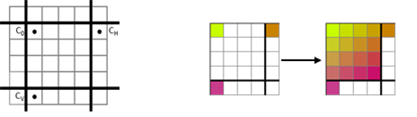
Figure 25. Base color position for ETC2-Planar block and decompression example.
Besides the RGB version, there is also a description of a punch through alpha version of ETC2 in OpenGL specifications, an RGBA8881 texture. There is no Individual block type, so the T-, H- and Planar modes are identified only by the presence of overflows. Diff-bit specifies Differential sub-modes. If it is "1", the Differential block is decompressed as before, and if "0", index "10" is reserved for the fully transparent color (see Table 7). The decoding procedure of T-, H- and Planar blocks stays unchanged.
|
N |
0 |
1 |
2 |
3 |
4 |
5 |
6 |
7 |
|
Luminance 00 |
0 |
0 |
0 |
0 |
0 |
0 |
0 |
0 |
|
Luminance 01 |
8 |
17 |
29 |
42 |
60 |
80 |
106 |
183 |
|
Luminance 10 |
T |
T |
T |
T |
T |
T |
T |
T |
|
Luminance 11 |
-8 |
-17 |
-29 |
-42 |
-60 |
-80 |
-106 |
-183 |
Table 7. The luminance codebook for ETC2 "punch through alpha". (T – transparent).
ETC2 cannot maintain a full-fledged alpha channel, necessary for many types of textures. Moreover, ETC2 does not support high-quality compression for two-component images, making it unsuitable for normal maps. For such cases, the 64-bit block named EAC is used. EAC encodes a single-channeled 4x4 tile with high accuracy. The following formats, which include EAC as a sub-block, are defined in OpenGL:
•COMPRESSED_RGBA8_ETC2_EAC / COMPRESSED_SRGB8_ALPHA8_ETC2_EAC (an analogue of BC3) – Is a 128-bit block consisting of 64-bit ETC2 block storing RGB channels and 64-bit EAC block storing alpha channel.
•COMPRESSED_R11_EAC / COMPRESSED_SIGNED_R11_EAC (an analogue of BC4) – Is a single 64-bit EAC block storing red channel.
•COMPRESSED_RG11_EAC / COMPRESSED_SIGNED_RG11_EAC (an analogue of BC5) – is a 128-bit block consisting of two 64-bit EAC blocks storing red and green channels.
For the sake of brevity, we’ll only describe the COMPRESSED_RGBA8_ETC2_EAC block in full detail. All ETC and EAC options are described in details in OpenGL 4.4 Core Profile specifications (42).
The EAC compression scheme repeats the ideas used in ETC, but for a single-component image: only one base value is stored for entire 4x4 tile, and per-texel indices are used to modulate its "luminance" (see Figure 26). As before, there is a predefined luminance codebook (see Table 8). An index of a particular luminance set (N) is directly stored in a compressed block. The only new addition is that the value of luminance modifier is multiplied by the Mul value, which is also directly stored in a compressed block. Altogether, the texel value is calculated using Equation 3.2, where the clamp255 clamps the value to a number in the [0, 255] range.
![]() (3.2)
(3.2)
Base value is stored with full 8-bit precision (see Figure 26). 3-bit indices are used, therefore up to eight different values are available in the local palette.
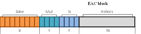
Figure 26. EAC block layout.
|
N |
0 |
1 |
2 |
3 |
4 |
5 |
6 |
7 |
8 |
9 |
10 |
11 |
12 |
13 |
14 |
15 |
|
Luminance 000 |
3 |
-3 |
-2 |
-2 |
-3 |
-3 |
-4 |
-3 |
-2 |
-2 |
-2 |
-2 |
-3 |
-1 |
-4 |
-3 |
|
Luminance 001 |
-6 |
-7 |
-5 |
-4 |
-6 |
-7 |
-7 |
-5 |
-6 |
-5 |
-4 |
-5 |
-4 |
-2 |
-6 |
-5 |
|
Luminance 010 |
-9 |
-10 |
-8 |
-6 |
-8 |
-9 |
-8 |
-8 |
-8 |
-8 |
-8 |
-7 |
-7 |
-3 |
-8 |
-7 |
|
Luminance 011 |
-15 |
-13 |
-13 |
-13 |
-12 |
-11 |
-11 |
-11 |
-10 |
-10 |
-10 |
-10 |
-10 |
-10 |
-9 |
-9 |
|
Luminance 100 |
2 |
2 |
1 |
1 |
2 |
2 |
3 |
2 |
1 |
1 |
1 |
1 |
2 |
0 |
3 |
2 |
|
Luminance 101 |
5 |
6 |
4 |
3 |
5 |
6 |
6 |
4 |
5 |
4 |
3 |
4 |
3 |
1 |
5 |
4 |
|
Luminance 110 |
8 |
9 |
7 |
5 |
7 |
8 |
7 |
7 |
7 |
7 |
7 |
6 |
6 |
2 |
7 |
6 |
|
Luminance 111 |
14 |
12 |
12 |
12 |
11 |
10 |
10 |
10 |
9 |
9 |
9 |
9 |
9 |
9 |
8 |
8 |
Table 8. Mod value codebook for EAC.
For example, consider a compressed block, where the base = 1101 11102, mul = 10102, N = 11012 and the index for the particular texel is 0012. After translation to decimals, base = 222, mul = 10, N = 13. In our case N corresponds to a luminance set {-1, -2, -3, -10, 0, 1, 2, 9} (column 13 in Table 8) and the texel index 0012 picks mod value from this set, mod = -2. After substituting the values into Equation 3.2, A=clamp255(222 + 10 × (-2)) or A=202.
The PVRTC (PowerVR Texture Compression) format (14) was designed for a family of PowerVR graphics cores and patented by Imagination Technologies (43) (44) (45) (46). It is used in Apple mobile devices, such as iPhones and iPads. The enhanced version called PVRTC2 was recently introduces for the new graphic cores. Both formats are supported by the OpenGL ES IMG_texture_compression_pvrtc (47), IMG_texture_compression_pvrtc2 (48) and EXT_pvrtc_sRGB (49) extensions. The appropriate WebGL draft extension is known as (50).
Perhaps, PVRTC format is the most undisclosed technology among the others mentioned in this article. Besides the original PVRTC paper «Texture Compression using Low-Frequency Signal Modulation» by Simon Fenney (14) and a few blog posts on Imagination Technologies site (51) (52) (53), there is no publicly available technical information. Even the OpenGL and WebGL extension specifications do not provide any implementation details. Nevertheless, R. Geldreich, a developer of the texture compression library named crunch, makes some efforts for PVRTC compressor implementation (54) (55).
PVRTC compression technique is very interesting and far away from everything mentioned before. Strictly speaking, PVRTC is not a block codec. The main idea has something in common with a wavelet compression, in which whole image is divided into high frequency and low frequency signals. A low frequency signal is represented by two low-resolution images A and B, scaled down by a factor of 4 in both dimensions. A high frequency signal is a full-resolution but low precision modulation signal M. To unpack a whole image, images A and B should be upscaled at first, and then blended using the modulation signal M, which specifies a per-texel blending weights (see Figure 27).
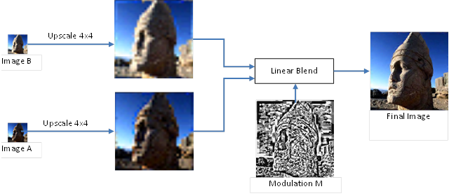
Figure 27. The core idea of PVRTC. (Source: PVRTC Paper (14))
Unlike other compression schemes, such approach benefits from exploiting similarity of colors across the block boundaries. Therefore, PVRTC natively supports smooth gradients. In addition, compressed textures do not have block artifacts. Furthermore, PVRTC takes an advantage out of correlation of actual texel position and its color value. BC- and ETC-like schemes exploit similarity of colors inside a block, but only color set matters and not the location of particular colors. That is, all texels in a tile could be randomly rearranged, and a BC codec can produce exactly the same local palette. However, PVRTC can loss some high frequency details in a compressed texture.
Imagination Technologies has added PVRTC2 support to their recent families of PowerVR graphics cores – PowerVR Series5XT and PowerVR Series6 (51) (52) (53). Both versions, PVRTC and PVRTC2, have 4bpp and 2bpp modes.
Naming confusion took place with the release of PVRTC2. After introduction of the original PVRTC format, PVRTC2 and PVRTC4 abbreviations became quite popular labels for 2bpp and 4bpp modes respectively. However, one of these abbreviations matches with the name of a new format. It is recommended to use the following aliases: PVRTC 4bpp, PVRTC 2bpp, PVRTC2 4bpp, PVRTC2 2bpp (or PVRTCII 2bpp/4bpp).
From a performance standpoint, accessing three different images for unpacking a single texel or tile is not a good idea. Therefore, all data stored in one place with block of 64 bits. Every block consists of one pixel of image A, one pixel of image B, and a corresponding 4x4 region of modulation coefficients (see Figure 28).
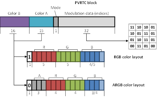
Figure 28. PVRTC 4bpp block layout.
Any of the A and B colors may be stored in RGB or RGBA format. The highest bit in both color fields determines which of formats are used. However, color field A is one bit smaller, than color field B. Therefore, color A can be encoded in RGB554 or ARGB3443 formats, and color B in RGB555 or ARGB3444 formats.
Generally, four adjacent PVRTC blocks have to be read for unpacking arbitrary texel (see Figure 29). It is necessary to restore corresponding areas of upscaled A and B images. Information from 4 adjacent PVRTC blocks is enough to decode 5x5 tile. Decoding example is shown in Figure 30.
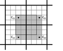
Figure 29. Texture
region that could be decoded
using four neighbor PVRTC blocks.
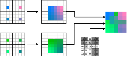
Figure 30. PVRTC 4bpp decoding example.
Upscaling is performed using a bilinear filter. Then, A and B images are blended using per-texel indices to determine a blending weight (see Table 9). Mode-bit (see Figure 28) is used for punch through alpha mode. This allows encoding of a 1-bit alpha channel without loss of precision for RGB channels. When Mode-bit is "1", index "10" is reserved for the fully transparent value.
|
Index (modulation data) |
Modulation value (Mode=0) |
Modulation value (Mode=1) |
|
00 |
0/8 |
0/8 |
|
01 |
3/8 |
4/8 |
|
10 |
5/8 |
4/8 (+ «punch through alpha») |
|
11 |
8/8 |
8/8 |
Table 9. Modulation values used in PVRTC decompression.
It is interesting to note, that despite of basic ideas dissimilarity, BC1 scheme could be treated as a special case of PVRTC, where upscaling is performed using a step function.
It may seem that reading of the four blocks could greatly affect performance. The negative effect is reduced by a texture cache, since fewer memory accesses are required for adjacent areas. Moreover, bilinear and more sophisticated types of filtering are essential for 3D rendering. Therefore, every texture fetch operation requires at least 2x2 source texels. When these texels lie in adjacent tiles, two or four blocks must be read in case of BC/ETC compression. The worst case requires four blocks for any of PVRTC, BC or ETC schemes.
The compression procedure is complicated due to the large influence area of a single block. Modifying a single base color (either A or B) can change any of the nearest 7x7 texels (see Figure 31). This feature complicates dynamic texture compositing and creation of texture atlases. Therefore, individual elements of the texture atlas must be padded with a border.
Figure 31. The influence area of one PVRTC block.
PVRTC format has a mode with a very high compression level of 2bpp. It is similar to the 4bpp mode and uses the same block layout (see Figure 32). However, the images A and B are further scaled down by a factor of two in the horizontal dimension. Therefore, 32-bit modulation field must hold modulation information for 8x4 texels. Mode-bit is now specifies the modulation data encoding. If it is "0", then per-texel 1-bit indices are stored in the modulation field. Otherwise, 2-bit indices are stored, but only for a half of the texels arranged in a chessboard pattern. Modulation values for remaining texels are computed by averaging the neighboring two or four modulation values.
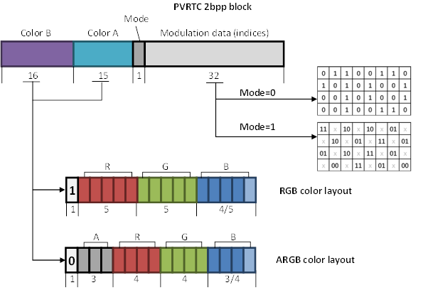
Figure 32. PVRTC 2bpp block layout.
The simplified example of PVRTC 2bpp decoding is shown in Figure 33. It is assumed that the "Mode" bit is "0" in all four compressed blocks.
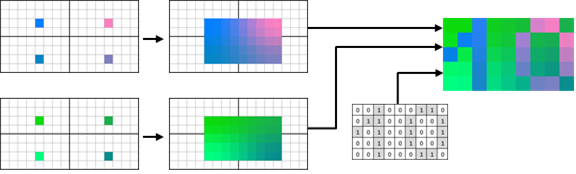
Figure 33. PVRTC 2bpp (Mode=0) decoding example.
PVRTC2 format improves quality and eliminates some shortcomings of the PVRTC. For example, PVRTC2 supports NPOT-textures (Non Power Of Two), where the resolution in one or both dimension is not a power of two. This feature has no direct relation with a compression scheme, but requires some hardware support. In particular, hardware should be able to calculate correctly the address of the requested compressed block.
Similarly to previous cases, an improvement of the quality is achieved by introducing new types of blocks or decoding modes. In PVRTC, each of base colors A and B can choose RGB or ARGB storage formats independently. However, it is far more common that both colors have the same format. Thus, only one bit (Opacity) is used in PVRTC2 to specify the format of both colors, and the second bit (Hard) is used to encode new modes (see Figure 34).
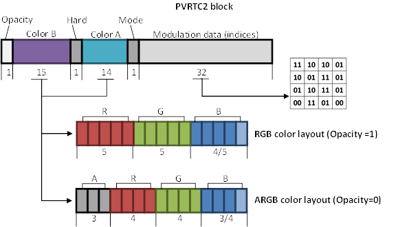
Figure 34. PVRTC2 block layout.
"Hard" bit along with "Mode" bit allows to specify one of the four decoding modes (see Table 10).
|
«Hard» bit |
«Mode» bit |
Decoding mode |
|
0 |
0 |
Standard bilinear interpolation |
|
0 |
1 |
Punch-through alpha |
|
1 |
0 |
Non-interpolated |
|
1 |
1 |
Local palette |
Table 10. PVRTC2 4bpp block modes.
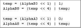
"Standard bilinear interpolation" and "Punch-through alpha" modes are decoded in the same way as previous PVRTC modes, except of some small changes in alpha. Now, the transparent index in "Punch-through alpha" mode is also sets the color values to zero. This behavior conforms to a premultiplied alpha (see BC2 Block (DXT2/DXT3)). Such approach has advantages for blending and filtering. The other change is related to alpha value unquantization. Now, alpha values for A and B images are transformed to an 8-bit format in a slightly different manner, depicted in Listing 5; AlphaA3, AlphaB3 – are 3-bit packed alpha values, and AlphaA8, AlphaB8 - unpacked 8-bit values. It is enquiring but not an issue, that AlphaA8 can never be "255", and AlphaB8 be "0".
Listing 5. Alpha convention to 8-bit value used in PVRTC2 decompression.
New modes, in which "Hard" bit is set to "1", simplify the creation of texture atlases and improve the quality for some difficult for PVRTC blocks. In the "No interpolation" mode, images A and B are upscaled without interpolation. Instead, all corresponding pixels have the same base color. The subsequent decoding process is the same as that in PVRTC. It must be marked, that the "Hard" flag affects the 4x4 texels region with offset [2, 2] (see Figure 35). For the boundary blocks, the "Hard" flag area is wrapped around, as if the texture mapping was toroidal.
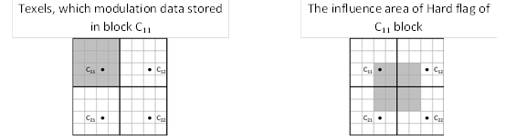
Figure 35. The influence area of Hard flag.
Decoding example for this mode is shown in Figure 36. This mode is analogue to S3TC compression. Indeed, if all the neighboring blocks had flags Hard=1 and Mode=0, then decoding of texels, corresponding to one PVRTC block, would replicate the BC1 decoding scheme. Thus, this mode can be used for encoding boundaries of individual elements in a texture atlas.
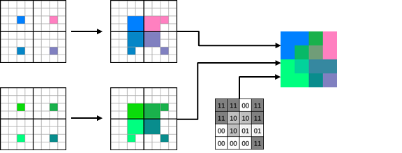
Figure 36. PVRTC2 decoding example for Hard=1, Mode=0 (no interpolation).
In the "Local palette" mode (Hard=1, Mode=1), the blending of A and B does not occur. Local palette is populated by A and B pairs from the four adjacent PVRTC2 blocks with eight colors totally. However, an index size is only 2 bits, meaning that only 4 of these 8 colors are available for every particular texel. Color sets, available for every texel, are shown in Figure 37, where the four PVRTC2 blocks, needed for decoding, are depicted. Block P specifies the decoding mode for texels shaded gray. A and B colors stored in each block are denoted as Pa, Pb, Qa, Qb, Ra, Rb, Sa, Sb. Colors, available for every texel, are depicted on the enlarged 4x4 region. The only exception is the most upper left texel P* – its colors are obtained by blending Pa and Pb.
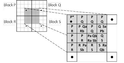
Figure 37. Per-texel
available colors for local palette mode.
(Source: US Patent 8526726 (46))
ASTC (Adaptive Scalable Texture Compression) was jointly developed by ARM and AMD and presented in 2012 (56). Format specifications (57) were approved by Khronos consortium and adopted in OpenGL. Appropriate OpenGL and OpenGL ES extension is called KHR_texture_compression_astc_hdr (58). All ARM graphics cores have ASTC hardware support since Mali-T628 and Mali-T678 (59). Patents (60) (61) (62) (63) belong to ARM. Nevertheless, ASTC is completely open and royalty-free format.
Each use case imposes its own requirements on the compression scheme:
•From 1- to 4-component textures support. While one-channel texture can be stored using BC7, PVRTC2 or ETC2, a lot of bits would be wasted for empty channels.
•Acceptable quality in case of uncorrelated channels. It is important for normal maps and RGBA images.
•LDR and HDR support. BC6H could be used for HDR texture compression, but it does not support alpha channel.
•Cross-platform. In particular, PVRTC is only available on the iOS platform, BC6H/BC7 is missing in mobile devices and ETC is not supported by desktop GPUs. For developers of cross-platform applications it is very inconvenient, to say the least.
•Bitrate/quality ratio flexibility. Depending on the texture type, different levels of compression artifacts are acceptable, as compressibility varies from image to image. Previously mentioned formats provide no more than two bitrate/quality options (BC1/BC7 or PVRTC 4bpp/2bpp). Since, the 5bpp compression level cannot be used (if 4bpp gives marginally insufficient quality), 8bpp option has to be used. It doubles bandwidth without significant quality improvements.
•Support of 2D and 3D textures.
A new compression scheme was developed with consideration of all of these requirements. ASTC format has a fixed size 128-bit block. However, encoded tile size varies from 4x4 to 12x12 texels for 2D textures, and from 3x3x3 to 6x6x6 for 3D textures. All supported tile sizes and corresponding bit rates can be found in Table 11. The “Increment” column shows, that the bit rate is scalable in a very fine steps. Tile size is also referred to as a block footprint in the ASTC specification.
|
№ |
2D textures |
3D textures |
||||
|
Tile size |
Bit rate |
Increment |
Tile size |
Bit rate |
Increment |
|
|
1 |
4x4 |
8.00 bpp |
125% |
3x3x3 |
4.74 bpp |
133% |
|
2 |
5x4 |
6.40 bpp |
125% |
4x3x3 |
3.56 bpp |
133% |
|
3 |
5x5 |
5.12 bpp |
120% |
4x4x3 |
2.67 bpp |
134% |
|
4 |
6x5 |
4.27 bpp |
120% |
4x4x4 |
2.00 bpp |
125% |
|
5 |
6x6 |
3.56 bpp |
114% |
5x4x4 |
1.60 bpp |
125% |
|
6 |
8x5 |
3.20 bpp |
120% |
5x5x4 |
1.28 bpp |
125% |
|
7 |
8x6 |
2.67 bpp |
105% |
5x5x5 |
1.02 bpp |
120% |
|
8 |
10x5 |
2.56 bpp |
120% |
6x5x5 |
0.85 bpp |
120% |
|
9 |
10x6 |
2.13 bpp |
107% |
6x6x5 |
0.71 bpp |
120% |
|
10 |
8x8 |
2.00 bpp |
125% |
6x6x6 |
0.59 bpp |
- |
|
11 |
10x8 |
1.60 bpp |
125% |
|||
|
12 |
10x10 |
1.28 bpp |
120% |
|||
|
13 |
12x10 |
1.07 bpp |
120% |
|||
|
14 |
12x12 |
0.89 bpp |
- |
|||
Table 11. ASTC tile sizes and bit rates.
ASTC is the most flexible format among described in our article, because it also supports LDR, HDR, 2D and 3D textures with up to 4 components. It even supports bit rates lower than 1bpp.
Conceptually, ASTC is similar to S3TC/BC7: up to four endpoint pairs and interpolation weights are stored in a compressed block, only predefined partitions are supported and particular partitioning is specified by the partition ID, which is also stored in a block. In case of a weak correlation, independent index table is stored for that channel. Each separate encoding is referred to as a plane.
Perhaps, the main and the most interesting ASTC innovation is the technique for encoding integer values with a fractional number of bits, called BISE. At the same time, BISE could be efficiently implemented in hardware.
Bounded Integer Sequence Encoding (BISE)
Bounded Integer Sequence Encoding, or BISE, addresses the following abstract problem: given sequences of equiprobable symbols from an alphabet of size N, find an encoding that allows the i-th symbol to be extracted in constant time with minimal hardware, allows the same hardware to be used with alphabets of many different sizes, and is storage-efficient (64) (56).
For example, consider a sequence of 5 integer values, which can be 0, 1 or 2. In case of a standard binary encoding, it is necessary to allocate 2 bits per value, 10 bits total. However, the number of distinct sequences is 35=243 and it is less than 28=256. Therefore, it is possible to encode entire sequence using 8 bits, providing a bit rate of 1.6 per value. In other words, five trits (trinary digits) can be represented using eight bits.
Now, consider a
sequence of arbitrary length, where each value belongs to range [0, N-1], where
N=3*2n. Each value can be represented using one trit and n bits. For
example, if N=12, any value can be represented in the form of ![]() , where
t is a trit, b0 and b1 are bits. The whole sequence can
be partitioned into groups of five values, padding the last group with zeros if
necessary. In binary form, a particular group can be represented as a bit
string
, where
t is a trit, b0 and b1 are bits. The whole sequence can
be partitioned into groups of five values, padding the last group with zeros if
necessary. In binary form, a particular group can be represented as a bit
string ![]() , where
ti
is a two-bit representation of a trit, and Bi are remaining lower
bits of a single value. These five trits can be stored using eight-bit string
T. If trit information remains interleaved with bit information, the group of
five values can be represented as a bit string
, where
ti
is a two-bit representation of a trit, and Bi are remaining lower
bits of a single value. These five trits can be stored using eight-bit string
T. If trit information remains interleaved with bit information, the group of
five values can be represented as a bit string ![]() , where
T[i:j] are individual bits of T. This string is 2 bits shorter than
the original.
, where
T[i:j] are individual bits of T. This string is 2 bits shorter than
the original.
It turns out,
that such encoding preserves trailing zeros. For example, if last group in our
sequence was padded with two zeros (so that ![]() and
and ![]() are
zeros), then
are
zeros), then ![]() and
and ![]() are
also zeros and they do not have to be stored. Thus, the sequence of any length,
with values ranging from 0 to 3*2n-1 , can
be encoded at a bit rate, that is close to a theoretical minimum. At the same
time, any arbitrary value can be rather easily extracted with minimal hardware.
are
also zeros and they do not have to be stored. Thus, the sequence of any length,
with values ranging from 0 to 3*2n-1 , can
be encoded at a bit rate, that is close to a theoretical minimum. At the same
time, any arbitrary value can be rather easily extracted with minimal hardware.
The same reasoning can be applied to a sequences, where N=5*2n. Here, three quints (base five digits) can be encoded using seven bits, since 53=125 is less than 27=128. Therefore, BISE technique, which uses trits and quints, is storage efficient (see Figure 38).
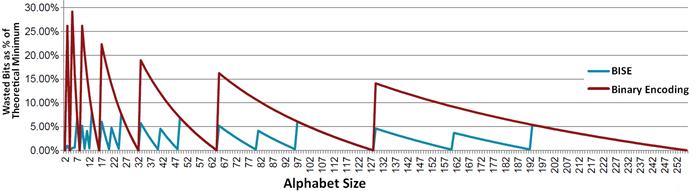
Figure 38. Storage efficiency of ISE and binary encoding. (Source: ASTC intro at CGDC2013 (65))
ASTC compression scheme uses BISE for encoding the color endpoints and interpolation weights. As a bonus, it also gives hardware-friendly power of two divisors for interpolation weights. A trit encodes one of three weights of {0, ½, 1} , and a quint encodes one of five weights of {0, ¼, ½, ¾, 1} . Moreover, BISE allows fine-grained varying of the endpoint precision. All cases, in which trits or quints are used for color endpoint encoding, are depicted in Table 12.
|
Range |
Number of used digits |
Bit size |
|||
|
Trits |
Quints |
Bits |
Effective |
Theoretical Minimum |
|
|
0..5 |
1 |
|
1 |
~ 2.60 |
2.58 |
|
0..9 |
|
1 |
1 |
~ 3.33 |
3.32 |
|
0..11 |
1 |
|
2 |
~ 3.60 |
3.58 |
|
0..19 |
|
1 |
2 |
~ 4.33 |
4.32 |
|
0..23 |
1 |
|
3 |
~ 4.60 |
4.58 |
|
0..39 |
|
1 |
3 |
~ 5.33 |
5.32 |
|
0..47 |
1 |
|
4 |
~ 5.60 |
5.58 |
|
0..79 |
|
1 |
4 |
~ 6.33 |
6.32 |
|
0..95 |
1 |
|
5 |
~ 6.60 |
6.58 |
|
0..159 |
|
1 |
5 |
~ 7.33 |
7.32 |
|
0..191 |
1 |
|
6 |
~ 7.60 |
7.58 |
Table 12. Color unquntization parameters.
After BISE-decoding, unpacked values are unquantized to a standard range [0, 255].
Partitioning was also improved in ASTC. While BC6H and BC7 compression schemes use predefined partition set table (see Figure 13), such approach is unsuitable for ASTC due to a large number of supported tile sizes, greater number of supported regions and increased size of Partition ID field (10 bit versus 6 bit in BC7). Instead, partition pattern is generated using a special hash function, which assigns a partition index to each texel. This function takes the texel's position inside a tile, Partition ID, tile size and the number of partitions as the input, and outputs a partition index. This function is simple enough to be implemented in hardware and the same function is used for 3D textures. All partition patterns for 8x8 tiles are depicted in Figure 39.
Figure 39. ASTC
partition sets for 8x8 tiles.
(Source: ARM Mail Graphics blogs (66))
One more specific feature of ASTC is the way interpolation weights are encoded. S3TC family schemes use per-texel indices to set an interpolation weight. Depending on block type, the size of the index can be 2, 3 or 4 bits. However, even 1-bit per-texel indices for a 12x12 tile do not fit into a 128-bit block. Therefore, ASTC proposes an independent grid size for weights and for texels. For example, only a 4x6 weight grid can be stored for a 12x12 tile. During the decoding stage, a weight grid is bilinearly upscaled to a tile size. However, it is not similar to the simple tile scaling, as it may seem. For example, smooth gradients can be usually represented with a small weight grid, like 2x2. Therefore, more bits are available for the endpoints. At the same time, sharp edges and color transitions could be encoded using an appropriate partition pattern. The size of a weight grid is chosen on a per block basis. Thus, tiles with strong vertical features may be encoded with a 4x2 or an 8x4 weight grid.
All this configuration data (grid size, number of partitions, endpoints format) has to be stored in a compressed block. While having to take some of the color data bits away and thus may degrading the image quality, this approach brings excellent flexibility, which actually greatly enhances the compression quality. ASTC allows different bit tradeoffs in each block and any particular tile can be encoded using the most suitable spreading of bits across partitions, endpoints and weights. Turns out, ASTC provides better quality than PVRTC, BC1-BC5 and ETC even at lower bit rates. The gain, in terms of PSNR, averages from 1.5 to 2 dB, whereas 0.25 dB is visible for most observers. BC6H have comparable quality, while BC7 outperforms ASTC by 0.5 dB at average. However, at 8bpp both the ASTC and the BC7 compressed images have PSNR quality around 45 dB, and the difference is very difficult to detect visually (56).
Moreover, ASTC is the first standard compression scheme for 3D textures, which exploits color correlation across all three dimensions. The nVidia's VTC extension for OpenGL (26) is also aimed at 3D textures, but it simply divides a 3D tile into 2D slices, which are compressed using BC1 scheme. In contrast, ASTC compresses the whole 3D tile using a 3D weight grid and partitioning, using a partition pattern generator. However, the weight grid is upscaled using simplex method instead of a trilinear interpolation (67). The whole 3D tile compression outperforms the sliced compression by 2 dB PSNR (68).
In addition, all features of ASTC are "orthogonal" in the sense, that any feature can be used independently from each other, e.g. it is possible to compress a 3D texture with two weakly correlated HDR channels.
There is a number of global decoding parameters, which are the same for any particular texture. Thus, there is no need to store theme in a compressed block:
•Dynamic range (LDR/HDR)
•Texture dimension (2D/3D)
•Tile size
•Output color space (sRGB/RGB)
While the data specified per block is as follows:
•Weight grid size
•Weight range (for BISE-decoding)
•Weight values
•Number of partitions
•Partition pattern ID
•Color endpoint modes
•Color endpoint data
•Number of planes (1 or 2)
•Plane-to-channel assignment
The texture may be encoded as a one-, two-, three- or four-channel image. But decoded values are always outputted in an RGBA format. Color values are returned as 8-bit integers in case of LDR sRGB mode, and as 16-bit floats otherwise. The ASTC block layout is depicted in Figure 40.
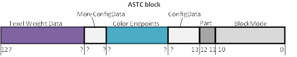
Figure 40. ASTC block layout.
All fields have variable length, except for “BlockMode” and “Part” fields.
The “Part” field specifies the number of partitions, decremented by one. For two-planes modes, number of partitions must be 1, 2 or 3. The “BlockMode” field specifies number of planes, weight range and size of weight grid. The “ConfigData” and “MoreConfigData” fields specifies endpoint mode for each of the endpoint pairs.
In case of 2D tiles, “BlockMode” consists of 5 fields: A, B, R, D, H (Table 13). A special void-extent mode has a separate encoding and is used for single-color tiles. Void-extent blocks also allow one to identify nearby regions of single color. This is used to short-circuit fetching of what would be identical blocks, and further reduce memory bandwidth.
Table 13. BlockMode field layout for 2D tiles. (Source: ASTC Specification (57))
The A and B fields specify the width (N) and height (M) of the weight grid. The D bit (double) is set to indicate dual-plane mode. The R field (range) and the H bit (high precision) specify the weight range (see Table 14). Note that, due to the encoding of the R field, bits R1 and R2 cannot both be zero to avoid ambiguity (see Table 13).
|
H |
R |
Range |
Number of used digits |
||
|
Trits |
Quints |
Bits |
|||
|
0 |
000 |
Invalid |
|
|
|
|
0 |
001 |
Invalid |
|
|
|
|
0 |
010 |
0..1 |
|
|
1 |
|
0 |
011 |
0..2 |
1 |
|
|
|
0 |
100 |
0..3 |
|
|
2 |
|
0 |
101 |
0..4 |
|
1 |
|
|
0 |
110 |
0..5 |
1 |
|
1 |
|
0 |
111 |
0..7 |
|
|
3 |
|
1 |
000 |
Invalid |
|
|
|
|
1 |
001 |
Invalid |
|
|
|
|
1 |
010 |
0..9 |
|
1 |
1 |
|
1 |
011 |
0..11 |
1 |
|
2 |
|
1 |
100 |
0..15 |
|
|
4 |
|
1 |
101 |
0..19 |
|
1 |
2 |
|
1 |
110 |
0..23 |
1 |
|
3 |
|
1 |
111 |
0..31 |
|
|
5 |
Table 14. Weight encoding parameters.
The “ConfigData” and “MoreConfigData” specify the encoding of endpoint pairs, each of which can have its own encoding mode. There are 16 such modes: 10 LDR formats and 6 HDR formats. However, HDR textures can use any of these. All of these endpoint formats are based on one of the following basic method:
•Independent. The two k-bit values are stored directly.
•Base+offset. (An analogue of ETC-differential encoding). The first value is stored directly using (k+1) bits, and is used as a base. The (k-1)-bit offset is used to obtain the second value.
•Base+scale. Two RGB values are represented by four numbers (R, G, B, s). The first color is equal to (R, G, B) and the second to (sR, sG, sB).
The detailed description of all endpoint modes and BISE encoding can be found in the ASTC specifications (57) and in original ASTC paper (56).
Conceptually, the decoding of the ASTC block is performed as follows. "BlockMode" field is used for determining the weight range and the size of weight grid. The weight data is read from the tail of a compressed block and is unpacked using BISE. After that, weights are unquantized to the [0, 64] range. If the weight grid size is less than tile size, bilinear interpolation is used for upscaling.
Afterwards, the "Part" field is used to determine the number of partitions. Partition pattern ID is read from the block and partition indices are generated for every texel using a hash function.
Given the number of partitions, the "ConfigData" and the "MoreConfigData" fields are used to calculate the total number of scalar values, that are used for endpoint encoding (endpoints can be specified with a different number of components, and a different number of values is used in different endpoint storage modes). However, the range of these scalar values has to be known for the BISE-decoding, since there is no explicit encoding of the range. After the weight and partition data decoding stage, the number of bits, available for color endpoints data, is known. The color endpoint values are always stored using the largest range of values that will fit into those bits. The endpoints are unpacked and unquantized.
An endpoint pair is chosen based on the partition index. These endpoint colors are blended using interpolation weights.
Brief description of all discussed texture compression formats
|
Format |
Block size |
Tile size |
Bit rate |
Quality |
Compressed components / Description |
|
BC1 (aka S3TC, DXT1) |
64 bit |
4x4 |
4bpp |
Medium |
RGB or RGB + 1-bit Alpha. Basic S3TC compression scheme. Bad at multicolor blocks and smooth gradients. Endpoints are stored in RGB565 format. |
|
BC2 (aka DXT2, DXT3) |
128 bit |
4x4 |
8bpp |
Medium |
RGBA BC1 + uncompressed 4-bit Alpha |
|
BC3 (aka DXT4, DXT5) |
128 bit |
4x4 |
8bpp |
Medium |
RGBA BC1 + BC4 compressed Alpha |
|
BC4 (aka ATI1, 3Dc+) |
64 bit |
4x4 |
4bpp |
Medium+ |
R Basic S3TC-like compression for a single channel. Endpoints are stored with 8-bit precision. |
|
BC5, (aka ATI2, 3Dc) |
128 bit |
4x4 |
8bpp |
Medium+ |
RG Two-channel compression using two BC4 blocks. Suitable for uncorrelated data like normal maps. |
|
BC6H |
128 bit |
4x4 |
8bpp |
Very high |
RGB (in FP16 format) BC7-like compression for HDR textures. Endpoints precision is 6 to 16 bits. |
|
BC7 |
128 bit |
4x4 |
8bpp |
Very high |
RGB, RGBA S3TC-based scheme enhanced with partition sets and multiple endpoints storage formats. High quality replacement of BC1-BC5 formats. Endpoints precision is (4+1) to (7+1) bits. |
|
PACKMAN |
32 bit |
2x4 |
4bpp |
Med/low |
RGB Compression is based on the luminance codebook. Bad at multicolor blocks. RGB444 endpoints. |
|
ETC, (aka iPACKMAN) |
64 bit |
4x4 |
4bpp |
Medium+ |
RGB Two PACKMAN blocks with enhanced encoding and new differential mode. |
|
ETC2 |
64 bit |
4x4 |
4bpp |
High |
RGB or RGB + 1-bit Alpha Further enhances ETC with 3 new block modes. Supports smooth gradients. Still bad at normal maps. |
|
EAC |
64 bit |
4x4 |
4bpp |
High |
R ETC-like compression for a single channel. An analogue of BC4. |
|
2x EAC |
128 bit |
4x4 |
8bpp |
High |
RG Two EAC blocks. An analogue of BC5. |
|
ETC2+EAC |
128 bit |
4x4 |
8bpp |
High |
RGBA An ETC analogue of BC3. |
|
PVRTC |
64 bit |
4x4, 8x4 (non-block) |
4bpp, 2bpp |
Medium+, Low |
RGBA, RGB or RGB + 1-bit Alpha Interesting non-block scheme. Supports smooth gradients out of box. Some problems with texture atlases. |
|
PVRTC2 |
64 bit |
4x4, 8x4 (non-block) |
4bpp, 2bpp |
High, Med/low |
RGBA, RGB or RGB + 1-bit Alpha Enhances PVRTC with 2 new block modes, which provides better quality and compositing/texture atlases support. |
|
ASTC |
128 bit |
4x4 to 12x12 3x3x3 to 6x6x6 |
0.89 – 8 bpp 0.59 – 4.74 bpp |
Any from low to very high |
R, RG, RGB, RGBA in both 8-bit and FP16 formats Most flexible all-in-one format. Supports LDR, HDR and 3D textures. Conceptually similar to BC7, but with very smart BISE encoding, block layout and other improvements. |
Table
15. Brief
description of all discussed texture compression formats
(obsoleted formats shaded with grey background)
The choice of a specific compression format is limited by target hardware. For example, the S3TC family is only available on PC. Depending on particular mobile platform, ETC or PVRTC may be supported (BC1-BC5 are supported by some devices, but it is uncommon). Only some newest mobile GPUs have support of the ASTC format.
Within the S3TC family:
•BC7 provides the best quality for RGB and RGBA textures and fully replaces BC2 and BC3 formats
•BC1 can be used for lower quality RGB compression
•BC4 and BC5 are used for one- and two-channel textures
•BC6H is used for HDR textures
PVRTC is obsoleted by PVRTC2, which improves the quality and solves some of the problems of its predecessor. PVRTC2 also supports RGB and RGBA textures.
ETC2 completely replaces PACKMAN and ETC formats, but supports RGB textures only. Moreover, certain combinations of ETC2 and EAC blocks provide the same functionality as the BC1-BC5 formats.
Finally, the ASTC format supports textures of any type and provides rich set of bit rates.
Texture compression takes an important place in modern computer graphics. Today, many smartphones have displays with FullHD resolution (1920x1080), and desktop GPUs are aimed at ultra-high definition like 4K and 8K (3840x2160 and 7680x4320 respectively), significantly increasing the memory bandwidth requirements. It is also expected that the texture's resolution will grow, making high compression ratios more and more important.
Since the acceptable level of compression artifacts varies across textures, choosing a compression bitrate on a per-texture basis can decrease the memory bandwidth usage, while retaining the image quality. Among the formats providing this opportunity, ASTC is the best one. While, it is not yet supported by desktop GPUs, we believe that ASTC will replace all other formats because of its flexibility and quality. At any given bitrate, ASTC outperforms all other formats in quality, except for BC7. Wide adoption of the ASTC will also simplify the development of cross-platform application.
As for the future of texture compression, it is possible that current methods will evolve by increasing both block and tile sizes. It is also possible that a variable bit rate (VBR) scheme will be implemented, further increasing the compression flexibility.
This work was supported by AMD (Advanced Micro Devices, Inc.) and partially financially supported by the Government of Russian Federation, Grant 074-U01. Authors would like to thank Vladimir Kibardin for his help in writing the English version of the article.
1.McDonald John. Eliminating Texture Waste: Borderless Ptex. 2013. GDC2013.
2.Inada T. and McCool M. D. Compressed lossless texture representation and caching. New York, NY, USA : ACM, 2006. Proceedings of the 21st ACM SIGGRAPH/EUROGRAPHICS symposium on Graphics hardware. pp. 111-120.
3.Strom Jacob and Akenine-Moller Tomas. PACKMAN: Texture Compression for Mobile Phones. . New York, NY, USA : ACM, 2004. ACM SIGGRAPH 2004 Sketches.
4.van Waveren, J.M.P. id Tech 5 Challenges: From Texture Virtualization to Massive Parallelization. Siggraph. Part of Beyond programmable shading course. 2009.
5.Olano M., et al., et al. Variable Bit Rate GPU Texture Decompression. 2011. Computer Graphics Forum, vol. 30, pp. 1299–1308.
6.Strom Jacob and Wennersten Per. Lossless Compression of Already Compressed Textures. Strom Jacob and Wennersten Per. s.l.: Eurographics Association. High Performance Graphics, 2011, pp. 177-182.
7.Vorobev Andrey. 3DGiTogi iyul 2001 goda — Vliyanie tekhnologii S3TC (FXT1) na kachestvo i skorost [3DGiTogi ]uly 2001 - impact of technology S3TC (FXT1) on quality and speed]. 2001. Available at: http://www.ixbt.com/video/0701i-video-s3tc1.html
8.WesleyandSmith Ian N., Liska Milos and Holub Petr. Implementation of DXT Compression for UltraGrid. Implementation of DXT Compression for UltraGrid. s.l. : CESNET, 2008.
9.Petr Holub, et al., et al. GPU-accelerated DXT and JPEG compression schemes for low-latency network transmissions of HD, 2K, and 4K video. Future Generation Computer Systems, vol. 29, № 8, 2013, pp. 1991-2006.
10.van Waveren, J.M.P. Real-Time DXT Compression. Id Software. 2006. Tech. rep.
11.FastDXT. Available at: http://www.evl.uic.edu/cavern/fastdxt/
12.Fast CPU DXT Compression. 2012. Available at: http://software.intel.com/en-us/vcsource/samples/dxt-compression
13.Ilya Perminov. Povyshenie effektivnosti obrabotki dinamicheski szhimaemykh tekstur [Improvement of Dynamic Texture Compression]. Nauchno-tekhnicheskiy vestnik informatsionnykh tekhnologiy, mekhaniki i optiki [Scientific and Technical Journal of Information Technologies, Mechanics and Optics], vol. 6 (88), 2013 г., стр. 164-165.
14.Fenney Simon. Texture compression using low-frequency signal modulation. Eurographics Association, 2003. Graphics Hardware. pp. 84-91.
15.Rover Camera Instrument Description. Available at: http://pdsimg.jpl.nasa.gov/data/mpfr-m-rvrcam-2-edr-v1.0/mprv_0001/document/rcinst.htm
16.Iourcha Konstantine I., Hong Zhou and Nayak Krishna S. System and method for fixed-rate block-based image compression with inferred pixel values. US Patent 5,956,431 US, 1999.
17.EXT_texture_compression_dxt1 extension specification. 2008. Available at: http://www.opengl.org/registry/specs/EXT/texture_compression_dxt1.txt
18.EXT_texture_compression_s3tc extension specification. 2013. Available at: http://www.opengl.org/registry/specs/EXT/texture_compression_s3tc.txt
19.EXT_texture_compression_rgtc extension specification. 2008. Available at: http://www.opengl.org/registry/specs/EXT/texture_compression_rgtc.txt
20.ARB_texture_compression_rgtc extension specification. 2009. Available at: http://www.opengl.org/registry/specs/ARB/texture_compression_rgtc.txt
21.EXT_texture_compression_latc extension specification. [Online] 2009. Available at: http://www.opengl.org/registry/specs/EXT/texture_compression_latc.txt
22.ARB_texture_compression_bptc extension specification. [Online] 2011. Available at: http://www.opengl.org/registry/specs/ARB/texture_compression_bptc.txt
23.Castano Ignacio. GPU DXT Decompression. 2009. Available at: http://www.ludicon.com/castano/blog/2009/03/gpu-dxt-decompression/
24.van Waveren, J.M.P. and Castano, Ignacio. Real-Time Normal Map DXT Compression. Real-Time Normal Map DXT Compression. 2008.
25.Brown Simon. DXT Compression Techniques. 2006. Available at: http://www.sjbrown.co.uk/2006/01/19/dxt-compression-techniques/
26.NV_texture_compression_vtc extension specification. 2004. Available at: http://www.opengl.org/registry/specs/NV/texture_compression_vtc.txt
27.Block Compression (Direct3D 10). Available at: http://msdn.microsoft.com/en-us/library/windows/desktop/bb694531
28.Blinn James F. Jim Blinn's Corner: Compositing, Part 1: Theory. IEEE-CGA, Vol. 14, 1994, pp. 83-87.
29.3Dc™ White Paper. Available at: http://www.hardwaresecrets.com/datasheets/3Dc_White_Paper.pdf
30.Texture Block Compression in Direct3D 11. Available at: http://msdn.microsoft.com/en-us/library/windows/desktop/hh308955
31.The OpenGL Graphics System: A Specification Version 4.2 (Core Profile). The OpenGL Graphics System: A Specification Version 4.2 (Core Profile). 2012.
32.Sovremennaya terminologiya 3D grafiki [Modern terminology 3D graphics]. Available at: http://www.ixbt.com/video2/terms2k5.shtml#hdr
33.OES_compressed_ETC1_RGB8_texture extension specification. 2008. Available at: http://www.khronos.org/registry/gles/extensions/OES/OES_compressed_ETC1_RGB8_texture.txt
34.WEBGL_compressed_texture_etc1 Extension Draft Specification. 2013. Available at: http://www.khronos.org/registry/webgl/extensions/WEBGL_compressed_texture_etc1/
35.The OpenGL Graphics System: A Specification Version 4.3 (Core Profile). The OpenGL Graphics System: A Specification Version 4.3 (Core Profile). 2013.
36.Strom Jacob and Akenine-Moller Tomas. iPACKMAN: High-quality, Low-complexity Texture Compression for Mobile Phones. New York, NY, USA : ACM, 2005. Proceedings of the ACM SIGGRAPH/EUROGRAPHICS Conference on Graphics Hardware. pp. 63-70.
37.Strom Jacob and Pettersson Martin. ETC2: Texture Compression Using Invalid Combinations. Aire-la-Ville, Switzerland : Eurographics Association, 2007. Proceedings of the 22Nd ACM SIGGRAPH/EUROGRAPHICS Symposium on Graphics Hardware. pp. 49-54.
38.Strom Jacob and Akenine-Moller Tomas. Multi-mode alpha image processing. US Patent 7,693,337 US, 2010.
39.Multi-mode image processing. US Patent 7,734,105 US, 2010.
40.Multi-mode image processing. US Patent 7,751,630 US, 2010.
41.Pettersson Martin and Strom Jacob. Texture compression based on two hues with modified brightness. US Patent 8,144,981 US, 2012.
42.The OpenGL Graphics System: A Specification Version 4.4 (Core Profile). The OpenGL Graphics System: A Specification Version 4.4 (Core Profile). 2013.
43.Fenney Simon. Method and apparatus for compressing data and decompressing compressed data. US Patent 7,236,649 US, 2007.
44.Method and apparatus for compressing data and decompressing compressed data. US Patent 7,242,811 US, 2007.
45.Method and apparatus for compressing data and decompressing compressed data. US Patent 8,204,324 US, 2012.
46.Method and apparatus for compressing data and decompressing compressed data. US Patent 8,526,726 US, 2013.
47.IMG_texture_compression_pvrtc extension specification. 2012. Available at: http://www.khronos.org/registry/gles/extensions/IMG/IMG_texture_compression_pvrtc.txt
48.IMG_texture_compression_pvrtc2 extension specification. 2012. Available at: http://www.khronos.org/registry/gles/extensions/IMG/IMG_texture_compression_pvrtc2.txt
49.EXT_pvrtc_sRGB extension specification. 2013. Available at: http://www.khronos.org/registry/gles/extensions/EXT/EXT_pvrtc_sRGB.txt
50.WEBGL_compressed_texture_pvrtc Extension Draft Specification. 2013. Available at: http://www.khronos.org/registry/webgl/extensions/WEBGL_compressed_texture_pvrtc/
51.Voica Alexandru. PVRTC: the most efficient texture compression standard for the mobile graphics world. [Online] January 2013. Available at: http://withimagination.imgtec.com/index.php/powervr/pvrtc-the-most-efficient-texture-compression-standard-for-the-mobile-graphics-world
52.Taking texture compression to a new dimension with PVRTC2. January 2013. Available at: http://withimagination.imgtec.com/index.php/powervr/pvrtc2-taking-texture-compression-to-a-new-dimension
53.Beets Kristof. Understanding PowerVR Series5XT: PVRTC, PVRTC2 and texture compression. June 2013. Available at: http://withimagination.imgtec.com/index.php/powervr/understanding-powervr-series5xt-pvrtc-pvrtc2-and-texture-compression-part-6
54.Geldreich Rich. PVRTC Compression - First Experiments. Available at: https://sites.google.com/site/richgel99/early-pvrtc-compression-experiments
55.PVRTC Compression - First Coded 4bpp. PVR Texture. Available at: https://sites.google.com/site/richgel99/pvrtc-compression2
56.Nystad, Jorn, et al., et al., Adaptive Scalable Texture Compression. Eurographics Association. High Performance Graphics, 2012, pp. 105-114.
57.Ellis Sean and Nystad Jorn. ASTC Specification. 2012.
58.KHR_texture_compression_astc_hdr extension specification. 2013. Available at: http://www.opengl.org/registry/specs/KHR/texture_compression_astc_hdr.txt
59.ARM Launches Second Generation of MALI-T600 Graphics Processors Driving Improved User Experience for Tablets, Smartphones and Smart-TVs. 2012. Available at: http://www.arm.com/about/newsroom/arm-launches-second-generation-of-mali-t600-graphics-processors-driving-improved-user-experience.php
60.Lassen Jorn and Nystad Anders. Method of and apparatus for encoding and decoding data. UK Patent Application 2491689 GB, 2012.
61.Method of and apparatus for encoding and decoding data. UK Patent Application 2491448 GB, 2012.
62.Method of and apparatus for encoding and decoding data. UK Patent Application 2491687 GB, 2012.
63.Method of and apparatus for encoding and decoding data. UK Patent Application 2491688 GB, 2012.
64.Nystad Jorn Lassen, Anders and Olson, Tomas. Flexible Texture Compression Using Bounded Integer Sequence Encoding. New York, NY, USA : ACM, 2011. SIGGRAPH Asia 2011 Sketches. pp. 32:1--32:2.
65.Ellis Sean. ARM ASTC Texture Compression. CGDC (China Game Developers Conference), 2013.
66.Smith Stacy. ASTC does it. 2013. Available at: http://community.arm.com/groups/arm-mali-graphics/blog/2013/10/22/astc-does-it
67.Gustavson Stefan. Simplex noise demystified. 2005. Available at: http://www.itn.liu.se/~stegu/simplexnoise/simplexnoise.pdf
68.Ellis Sean. More ASTC in ARM Mali GPUs – High Dynamic Range and 3D. 2013. Available at: http://malideveloper.arm.com/engage-with-mali/more-astc-in-arm-mali-gpus-high-dynamic-range-and-3d/